Edge computing transceivers: match optics to demand shifts
When edge computing workloads surge, the first bottleneck is often not compute, but links: optics that cannot scale reach, oversubscribe lanes, or survive the temperature swings in remote cabinets. This article helps IT directors and network engineers choose SFP and QSFP transceivers that stay stable as traffic patterns change. You will get a practical head-to-head comparison, a selection checklist, and field-tested troubleshooting for real deployments.

Edge computing optics vs core optics: what changes at the edge?
In centralized data centers, link budgets and thermal margins are usually generous. At the edge, you often operate in constrained enclosures with airflow limits, higher ambient temperature, and longer patch runs to sensors or micro-data rooms. That is why edge computing transceivers must be selected with a link budget mindset: wavelength, receive sensitivity, transmitter launch power, and fiber attenuation all interact. The IEEE 802.3 family defines electrical and optical requirements for Ethernet, while vendor datasheets define the actual module limits you must respect. anchor-text: IEEE 802.3 standard overview
Performance lens: lane rate, modulation, and reach
Edge sites commonly run 1G SFP, 10G SFP+, 25G SFP28, and sometimes 40/100G QSFP+ or QSFP28. Short-reach optics typically use multimode fiber (MMF) with OM3 or OM4, while long-reach uses single-mode fiber (SMF) with 1310 nm or 1550 nm. If your edge site will add cameras or stream processing, you want optics that tolerate higher BER conditions over time and fiber aging. In practice, the module’s specified minimum receiver sensitivity and the system’s link margin are what keep links up during demand spikes.
Reliability lens: operating temperature and enclosure airflow
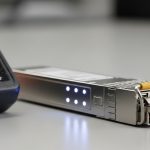
Many field failures come from thermal stress rather than “bad optics.” A module rated for 0 to 70 C may work on a bench but fail in an outdoor or poorly ventilated cabinet. For edge computing, prioritize modules with an industrial temperature range such as -40 to 85 C when the site design cannot guarantee cooling. Vendor datasheets for SFP and QSFP modules clearly list this; if you do not plan for it, you will see intermittent link flaps under seasonal load.
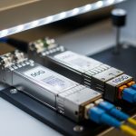
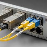
Head-to-head: SFP+ 10G SR vs SFP28 25G SR vs QSFP28 100G SR
Below is a practical comparison for edge computing where you might start with 10G and later expand to 25G or 100G without redesigning the entire fiber plant. Assume you are using MMF (OM4) for short reach within a site, and you want predictable behavior for dynamic demand. Always validate with your switch vendor’s compatibility list and the module’s DOM (Digital Optical Monitoring) support.
| Module type | Typical part examples | Wavelength | Reach (MMF) | Data rate | Connector | DOM | Typical power | Operating temp |
|---|---|---|---|---|---|---|---|---|
| SFP+ 10G SR | Cisco SFP-10G-SR, Finisar FTLX8571D3BCL, FS.com SFP-10GSR-85 | 850 nm | Up to ~300 m on OM3 / up to ~400 m on OM4 (varies by vendor) | 10.3125 Gb/s | LC | Usually supported | ~0.8 to 1.5 W | Often 0 to 70 C (check exact SKU) |
| SFP28 25G SR | Common 25G SR offerings from major OEMs and third parties | 850 nm | Up to ~100 m on OM3 / ~150 m on OM4 (varies) | 25.781 Gb/s | LC | Usually supported | ~1.2 to 2.5 W | Often -5 to 70 C or 0 to 70 C; industrial SKUs exist |
| QSFP28 100G SR | QSFP28 100G SR modules from switch OEM ecosystems | 850 nm | Up to ~100 m on OM4 (varies by vendor) | 103.125 Gb/s | LC (4x lanes) | Usually supported | ~3.5 to 6 W | Often -5 to 70 C; check industrial variants |
In edge computing, the “best” choice is rarely the highest spec on paper. It is the one that matches your fiber type and your enclosure’s thermal envelope while remaining compatible with your switch optics implementation. The moment you move from 10G to 25G, MMF reach can shrink, so you may need to shorten patch runs or upgrade to better OM4 plant. For long runs, SMF optics become more cost-effective over time because they preserve reach and reduce the number of intermediate patch points.

Compatibility and governance: avoiding optic surprises during scaling
Dynamic demand at the edge means you will add transceivers faster than you can rewrite governance. If your procurement process treats optics as “commodity,” you risk inconsistent vendor behavior across sites. Most enterprise switches expect standard-compliant modules, but vendor-specific quirks exist: DOM thresholds, supported speed grades, and how the switch handles LOS/alarms. Your governance should include approved module part numbers and a validation plan for each switch model and firmware revision.
What to standardize in your edge computing policy
- Switch compatibility matrix by model and firmware: capture which SFP/SFP28/QSFP SKUs pass.
- DOM telemetry requirements: ensure your monitoring stack can ingest temperature, bias current, and optical power.
- Optics lifecycle rules: define acceptable vendor replacements and how you handle end-of-life notices.
- Temperature class: require industrial-grade optics if cabinets lack predictable cooling.
Pro Tip: In the field, many “mystery link flaps” trace back to DOM alarm handling. Some switches log warnings but do not hard-fail; others trigger port resets when thresholds are exceeded. During an edge computing traffic surge, small thermal changes can push optical power or bias current near a vendor-specific threshold, so you must align your monitoring thresholds with the module’s datasheet values.
Selection criteria checklist for edge computing transceivers
Use this ordered checklist when you choose optics for sites that will evolve. It is written the way engineers tend to decide under budget and time pressure.
- Distance and fiber type: confirm OM3 vs OM4 vs SMF, then compute worst-case link budget using vendor receiver sensitivity and typical attenuation.
- Switch port capability: verify the exact transceiver type (SFP+, SFP28, QSFP28) and speed support on your switch model.
- DOM and monitoring integration: ensure your NMS reads and alerts on temperature, Tx power, Rx power, and link status.
- Operating temperature range: match module spec to cabinet ambient plus airflow assumptions; prefer industrial SKUs for uncontrolled environments.
- Budget and upgrade path: compare total cost for short-term 10G vs planned 25G/40G/100G growth; MMF reach constraints often drive the real cost.
- Vendor lock-in risk: define approved third-party options and test them; avoid mixing incompatible optics across the same switch family without validation.
- Failure mode tolerance: plan spares and define RMA lead times; optics are small, but downtime at the edge is expensive.
Common mistakes and troubleshooting that actually show up
Here are failure modes I have seen in operations where edge computing sites scale quickly. Each includes the root cause and what fixed it.
Link up on install, then flaps during peak
Root cause: thermal stress or marginal link budget. For SR optics, a slightly higher fiber attenuation from patch damage or dirty connectors can push the receiver near sensitivity limits as the module warms.
Solution: clean connectors with proper fiber cleaning tools, re-check fiber loss with an optical power meter or OTDR, and confirm module temperature rating against actual cabinet ambient. If needed, move to SMF or shorten patch runs.
DOM alarms but no clear cause in dashboards
Root cause: monitoring thresholds tuned for one vendor’s DOM behavior. Another vendor’s module may report different baseline values, triggering noisy alerts during normal operation.
Solution: pull DOM readings directly from the switch and compare them to the module datasheet ranges. Adjust alert thresholds and document the per-vendor baseline in your NMS runbooks.
“Compatible” optics still fail after firmware updates
Root cause: firmware changes in the switch optics stack: stricter compliance checks, different handling of FEC settings, or altered LOS behavior.
Solution: after firmware upgrades, run a validation script that cycles ports and verifies DOM telemetry stability. Keep a small pool of known-good optics per switch model, and include them in your change management checklist.
Wrong wavelength or fiber mismatch during expansion
Root cause: mixing 850 nm SR optics with SMF plant, or confusing OM3 and OM4 labeling during construction. In edge computing, expansion is often done by contractors who label by convenience, not by measured loss.
Solution: require measured fiber verification: document loss per link and connector type. Update your asset registry with measured outcomes, not just planned design.

Cost and ROI: what to budget for optics at the edge
Optics pricing varies widely by vendor and temperature grade. In many enterprises, 10G SR SFP+ modules often land in the low tens to low hundreds of dollars per unit depending on OEM vs third-party and industrial rating. 25G SFP28 and QSFP28 100G typically cost more, and the cost delta can be meaningful at scale across many edge sites.
ROI comes from avoiding downtime and reducing truck rolls. If a site fails during a maintenance window, the cost is not the optics module; it is the delayed service restoration, SLA penalties, and lost operational data. TCO also includes power and cooling: QSFP28 modules can draw several watts, which matters when cabinets are already near thermal limits. My governance recommendation is to buy fewer, higher-confidence optics SKUs, validate them once per switch model, and keep spares staged to reduce recovery time.
Which option should you choose?
Here is a clear recommendation by reader type, assuming you are building edge computing links that must handle shifting demand.
| Reader type | Best default choice | When to switch | Governance emphasis |
|---|---|---|---|
| Operations team with mixed switch generations | SFP+ 10G SR for short in-cabinet runs; industrial temperature where possible | Switch to SFP28 when growth demands 25G uplinks and MMF reach still fits | Strict compatibility matrix and firmware test plan |
| Network architect planning a 3 to 5 year edge roadmap | Standardize on SFP28 SR for MMF segments and SMF for longer distances | Use QSFP28 for aggregation where you need high fan-in without adding more ports | Asset registry with measured link loss and DOM monitoring baselines |
| Budget-conscious IT director with strict procurement cycles | OEM optics for first deployment sites; approved third-party optics only after validation | Move to third-party only where thermal and DOM behavior are proven stable | RMA lead time tracking and staged spares strategy |
If your edge computing sites will scale quickly, prioritize optics that match your fiber reality and your thermal envelope, not just the advertised reach. Next, map your current fiber plant and switch models into a compatibility matrix using the selection checklist above via edge computing.
FAQ
Q: Do I need DOM support for edge computing transceivers?
A: Yes, if you want proactive maintenance. DOM lets you alert on temperature, Tx power, and Rx power before links degrade. Even if the link stays up, early warning reduces downtime during demand spikes. Confirm your switch and monitoring system can ingest the DOM fields for that module type.
Q: Can I mix OEM and third-party optics across edge sites?
A: You can, but only after validation per switch model and firmware. Different vendors may report DOM values differently and can trigger alarms or port resets under the same threshold settings. Governance should require approved part numbers and a test record