Edge computing deployments live and die by latency, link stability, and power efficiency. This article helps network and field teams make confident transceiver selection choices for fast data processing nodes in harsh, space-limited locations. You will compare options that matter in real rollouts, from 10G SR optics to long-haul variants, and learn how to avoid the most common failure modes.

Latency and reach: how optical choice affects edge responsiveness
For edge computing, the transceiver selection decision is really a link budget and latency decision. IEEE 802.3 defines the electrical and optical interfaces for common Ethernet speeds, but your end-to-end behavior is dominated by distance, fiber type, and connector losses. In practice, teams often start with the required reach (for example, 300 m inside a micro-data hall versus 10 km across a campus) and then select a transceiver class that matches the budget with margin.
Short reach at the edge: SR and LR families
When edge nodes connect to nearby aggregation switches, short-reach optics are usually the most reliable and power-efficient. For 10G Ethernet, SR typically uses 850 nm multimode fiber and is commonly specified for 300 m to 400 m depending on OM grade and transceiver vendor. For 25G/40G/100G, SR variants use similar short-reach concepts but with different optics and encoding, so you must match the switch port capability and the fiber plant.
Long reach: LR and coherent considerations
If your edge site spans wider distances, LR-style optics (for example, 1310 nm single-mode) can extend reach to roughly 10 km in many deployments. Past that, long-haul or coherent solutions may be required, and they introduce stricter alignment, dispersion management, and sometimes higher power draw. Even when a transceiver claims a long reach, you should verify the specific link budget, including aging and temperature effects.
Performance head-to-head: 10G SR vs 10G LR vs 25G SR (what changes)
Below is a practical comparison for edge computing transceiver selection. Exact values vary by vendor and part number, so treat this as a field-oriented baseline and confirm with the datasheet for your exact model.
| Category | Typical wavelength | Fiber type | Common reach (class) | Connector | Data rate | Operating temp (typical) | Power draw (typical) |
|---|---|---|---|---|---|---|---|
| 10G SR | 850 nm | OM3/OM4 multimode | 300 m to 400 m | LC duplex | 10G Ethernet | 0°C to 70°C (varies) | ~0.5 W to 1.5 W |
| 10G LR | 1310 nm | Single-mode | ~10 km (class) | LC duplex | 10G Ethernet | -5°C to 70°C (varies) | ~0.8 W to 2.0 W |
| 25G SR | 850 nm | OM3/OM4 multimode | ~70 m to 100 m (varies) | LC duplex | 25G Ethernet | -5°C to 70°C (varies) | ~1.0 W to 2.5 W |
Field takeaway: SR optics often win on ease of installation and lower system complexity, while LR wins on distance. For edge computing, the “best” choice is usually the one that matches your fiber plant and keeps the optical power and receiver margin healthy across temperature cycles.

DOM and operational visibility
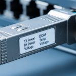
Most modern transceivers support Digital Optical Monitoring (DOM) over the standard management interface so you can read laser bias current, received optical power, and temperature. In edge environments, this matters because dust, vibration, and connector wear can change optical levels over time. When your transceiver selection includes DOM support, you can set proactive thresholds and alert before links flap during peak processing windows.
Pro Tip: During acceptance testing, record the baseline receive power (Rx) at commissioning and again after the first month in the field. In edge sites, connector micro-movement and cleaning variance can shift Rx power by a few dB, and proactive thresholding beats waiting for a “link down” event.
Compatibility and optics hygiene: the real edge constraints
Transceiver selection is not only about distance; it is also about compatibility. Switch vendors often enforce optics compatibility checks, including EEPROM/vendor IDs, supported standards, and sometimes specific optics calibration parameters. If you mix OEM and third-party modules, you can see link negotiation failures or higher-than-expected error counters even when the link “comes up.”
Match the switch port capability first
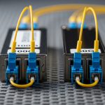
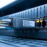
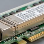
Start with port speed and form factor: SFP+ for 10G, SFP28 for 25G, QSFP+ for 40G, and QSFP28 for 100G-class designs. Then confirm whether the port expects SR, LR, or specific modulation formats. For example, Cisco-branded optics like Cisco SFP-10G-SR and Finisar-style 10G SR optics exist, but your switch may also accept FS.com or other equivalents if the vendor’s compatibility matrix allows it.
Fiber type and connector cleanliness
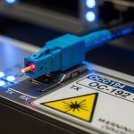
Multimode SR requires OM3/OM4 fiber in most modern deployments, and the transceiver selection must match the fiber grade and the patch panel loss. For long-haul LR on single-mode, you must ensure the fiber is truly single-mode and the connectors are properly cleaned. In field operations, the most common optical issue is not a “bad transceiver,” but contaminated connectors or mismatched patch cords.
Temperature and power budget
Edge racks often run hotter than office environments due to poor airflow and nearby compute. Many optics are specified for ranges such as 0°C to 70°C or -5°C to 70°C, but you should validate the transceiver’s threshold characteristics against your rack’s ambient and airflow. Also consider the total power budget: if you run dozens of ports at 25G, even a 1–2 W difference per module can add up.
Cost and ROI: OEM vs third-party in edge rollouts
On paper, third-party optics can reduce purchase cost, but the ROI depends on operational risk. In a typical edge rollout of 48 ports, a difference of even $20 to $60 per transceiver can matter, yet field replacement labor and outage time often dominate total cost. OEM modules may cost more, but they can reduce compatibility surprises and speed up troubleshooting when you have vendor support contracts.
Realistic TCO approach
For TCO, include module price, expected failure rate, cleaning supplies, spares inventory, and downtime cost. A practical approach is to stock a small “hot spare” pool for each optics class (SR and LR) and keep a validated list of compatible part numbers for each switch model. If you are deploying mixed vendor hardware, validate in a staging rack using the exact patch cords and transceiver models before scaling.
Examples of commonly referenced optics families include Cisco SFP-10G-SR and Finisar/Forti-style 10G SR modules such as Finisar FTLX8571D3BCL, and third-party equivalents like FS.com SFP-10GSR-85. Even with known part numbers, always confirm compatibility with your specific switch and firmware revision.
Decision checklist for transceiver selection in edge computing
Use this ordered checklist during planning and during site acceptance. It is designed to minimize rework and reduce the chance that an optics choice fails under edge conditions.
- Distance and fiber plant: confirm required reach and whether you have OM3/OM4 multimode or single-mode.
- Speed and form factor: verify SFP+/SFP28/QSFP variants match the switch port.
- Switch compatibility: check the vendor compatibility matrix for your switch model and firmware.
- DOM support: ensure the transceiver exposes temperature and Rx power so you can set alerts.
- Operating temperature: validate module spec versus rack ambient, airflow direction, and worst-case sun load.
- Optical budget margin: confirm link loss (fiber + splices + connectors) leaves margin for aging and cleaning variance.
- Vendor lock-in risk: plan a tested shortlist of approved third-party parts to avoid procurement delays.
- Spare strategy: stock the most failure-prone class based on your environment (usually short-reach with high patching churn).
Common mistakes and troubleshooting tips
Even experienced teams get tripped up. Here are concrete pitfalls that show up during edge deployments, with root causes and fixes.
“Link up” but high errors: mismatched optics or marginal power
Root cause: transceiver selection that is technically compatible but not aligned with your switch’s supported optical parameters can cause elevated BER or CRC errors. Another cause is insufficient optical power margin after connector wear. Solution: compare DOM Rx power readings to the vendor’s recommended range, reseat and clean LC connectors, and confirm the module’s exact part number against the switch compatibility list.
Immediate link failures after installation: dirty connectors
Root cause: contaminated fiber endfaces are the top real-world optical failure mode. In edge sites, dust from construction or vibration-driven micro-movement increases contamination. Solution: inspect with a fiber scope, clean with the correct consumables, and re-terminate or re-patch if you see scratches or persistent contamination.
Works indoors but fails in heat: temperature range mismatch
Root cause: using a transceiver specified for a narrower operating range than your enclosure conditions. Compute racks can exceed expected ambient temperatures during peak workloads. Solution: measure actual module temperature via DOM, improve airflow, and replace with optics rated for your worst-case environment.
Distance surprises: wrong fiber type or OM grade
Root cause: assuming “multimode is multimode.” OM2/OM3/OM4 differences can break SR reach assumptions. Solution: verify fiber grade at the patch panel, run a loss test with OTDR or qualified testers, and select SR modules matched to OM4 when needed.
Which option should you choose?
Your best transceiver selection depends on your edge topology and fiber plant. If you are connecting a nearby edge switch to aggregation within a micro-data room, choose SR optics for simplicity and cost-effective power usage. If your edge node spans a campus or remote facility, choose LR optics to preserve link stability over longer distances. For higher throughput edge backhauls, consider 25G SR only when your multimode plant supports the needed reach with margin; otherwise, move to single-mode options.
| Reader type | Typical edge scenario | Recommended transceiver selection | Why |
|---|---|---|---|
| Field engineer with mixed racks | Many patch changes, frequent maintenance | SR with strong DOM + validated compatibility list | Faster troubleshooting and better optical visibility |
| Network planner with new fiber builds | Consistent multimode or single-mode design | Match speed to fiber grade; SR for OM4, LR for SM | Predictable link budgets and fewer surprises |
| Operations team optimizing outages | Hot, dusty enclosures | Rated operating temp optics + proactive DOM thresholds | Prevents thermal and contamination-driven flaps |
| Procurement balancing budget and risk | Large-scale deployment at many sites | OEM for critical links; approved third-party for non-critical | Controls TCO without losing reliability |
FAQ
What should I verify first during transceiver selection for edge computing?
Confirm the switch port speed and form factor (SFP+/SFP28/QSFP) before choosing wavelength or fiber type. Then verify compatibility with your exact switch model and firmware, and ensure the fiber plant matches the intended standard (OM3/OM4 for SR, single-mode for LR).
Is DOM support really necessary at the edge?
DOM is not mandatory for basic link operation, but it is highly valuable for edge maintenance. With DOM, you can monitor Rx power and temperature and set alerts that catch degradation early, reducing downtime during processing peaks.
Can I use third-party transceivers without issues?
Often yes, but only after you validate compatibility for your switch. Some third-party modules can negotiate incorrectly or show higher error rates under specific conditions, so rely on the vendor’s compatibility guidance and run a staging test before scaling.
How do I avoid SR failures caused by fiber issues?
Verify OM grade at the patch panel and measure end-to-end loss using qualified tools. Also keep connector cleanliness consistent with inspection and cleaning workflows; in the field, dirty connectors can mimic “bad optics.”
What is a practical way to set thresholds using DOM?
Take commissioning baselines for Rx power and module temperature, then set alert thresholds based on observed variance plus vendor guidance. Re-check after the first month because edge sites often introduce connector movement and contamination changes early.
Should I prioritize cost or reliability for critical edge links?
For links that carry time-sensitive processing or safety-related telemetry, prioritize reliability and proven compatibility, even if OEM cost is higher. For non-critical links, approved third-party modules can be a reasonable TCO optimization when you have validated part numbers and spares.
If you want to tighten the whole process, pair transceiver selection with a fiber readiness workflow and acceptance testing plan. Next, explore fiber testing and acceptance for edge networks to reduce commissioning surprises and stabilize optical performance over time.
Author bio: I design and validate high-density network optics workflows for edge deployments, focusing on usability, monitoring, and field-proof troubleshooting. I have hands-on experience deploying SR/LR transceiver stacks across rugged racks, using DOM telemetry, link budget checks, and fiber inspection practices.