Edge computing deployments rarely look stable for long: traffic spikes at the site, backhaul links migrate, and hardware is swapped during maintenance windows. This article helps network teams make practical transceiver selection decisions for edge nodes that must scale with changing demand without surprise outages. You will learn how to match optics to fiber plant reality, switch compatibility, and operating constraints such as temperature and power budgets.
Why edge traffic changes break naive transceiver choices
In an edge site, you often provision links assuming a steady-state profile, then reality arrives: seasonal workloads, event-driven bursts, and failover paths that reroute traffic when WAN circuits degrade. A transceiver that works at room temperature on the bench can still fail in the field if the link budget is marginal, the fiber is older than expected, or the switch expects specific DOM behavior. IEEE-compliant optics still vary in transmitter power, receiver sensitivity, and thermal management, so the “same” part number from different vendors can behave differently.
Dynamic demand also changes the operational mix: you may shift from 25G to 10G during a staged upgrade, or move from direct-attached copper to fiber when distance grows. In practice, edge teams need optics that support the intended data rate, link reach, and monitoring features (DOM) so automation can react before the link drops. For standards grounding, consult IEEE 802.3 media access control and physical layer specifications and vendor datasheets for power and reach limits. IEEE 802.3 standard index
Transceiver types and fiber choices that fit edge backhaul
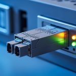
Most edge backhaul designs use fiber optics because they handle distance and EMI constraints better than copper in industrial or outdoor environments. The common categories you will see are SFP/SFP+ (typically up to 10G), SFP28/25G, and QSFP/QSFP28/QSFP56 (higher aggregate speeds). Your selection must align with the switch port type and the transceiver’s electrical interface expectations (for example, 1x or 2x lane mapping).
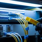
On the fiber side, the two dominant options are multimode (MMF) and single-mode (SMF). MMF is attractive for short runs because it is cheaper and easier to terminate, but it has stricter reach limits at higher speeds and requires correct modal bandwidth grade. SMF is the safe choice for longer reach and future scaling, but it demands careful splice and connector hygiene to protect the link budget.
| Transceiver family (examples) | Typical data rate | Wavelength | Reach class (typical) | Fiber type | Connector | DOM / monitoring | Operating temp (typical) |
|---|---|---|---|---|---|---|---|
| SFP-10G SR (Cisco SFP-10G-SR, FS SFP-10GSR) | 10G | 850 nm | Up to ~300 m (OM3/OM4 depends) | MMF | LC | Commonly supported | -5 to 70 C (varies by vendor) |
| SFP28-25G SR (common 25G SR optics) | 25G | 850 nm | Up to ~100 m over OM4 (depends on spec) | MMF | LC | Commonly supported | -5 to 70 C (varies by vendor) |
| SFP28-25G LR (example class) | 25G | 1310 nm | Up to ~10 km | SMF | LC | Commonly supported | -5 to 70 C (varies by vendor) |
| QSFP28-100G SR4 (example class) | 100G | 850 nm | Up to ~100 m (MMF) | MMF | MT-RJ or MPO (varies) | Commonly supported | -5 to 70 C (varies by vendor) |
| QSFP28-100G LR4 (example class) | 100G | 1310 nm | Up to ~10 km | SMF | LC or MPO (varies) | Commonly supported | -5 to 70 C (varies by vendor) |
In edge deployments, I treat MMF as a “short reach, tightly managed” option. If your termination quality is unknown, or the building fiber plant includes older OM2/low-grade runs, you will eventually pay the price in retransmits and link drops. If you need flexibility for dynamic demand, SMF with a conservative reach margin is typically easier to scale.

Selection criteria checklist for edge nodes under load swings
For transceiver selection at the edge, use an ordered checklist so your decision is reproducible during audits and spares planning. This is the same workflow I use when deploying new sites and when swapping optics during a phased upgrade.
- Distance and link budget: confirm fiber type, measured attenuation, splice loss, and connector loss; target at least a 3 to 6 dB margin beyond the vendor’s nominal reach.
- Data rate and lane mapping: match the switch port speed mode (for example, 10G vs 25G vs 100G) and ensure the transceiver supports the same breakout behavior.
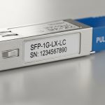
- Switch compatibility and coding: verify that the transceiver is supported by the switch vendor’s compatibility matrix; check whether the platform enforces specific EEPROM identifiers.
- DOM support and telemetry: confirm DOM type and fields (Tx power, Rx power, temperature, voltage) and validate that your monitoring stack can ingest it.
- Operating temperature and airflow: edge cabinets can exceed 50 C under sustained loads; choose optics rated for the environment and validate with a thermal plan.
- Vendor lock-in risk: decide whether you will standardize on OEM optics or use third-party modules with validated part numbers and known behavior.
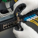
- Connector and cleaning readiness: ensure the field team can maintain LC or MPO cleanliness and has the correct cleaning tools for the fiber type.
- Power and budget: check transceiver power draw; in dense edge racks, transceiver heat adds up and can impact PSU margins.
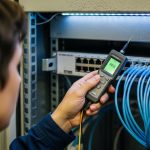
Pro Tip: In edge sites, the biggest “surprise” is not reach on paper; it is link budget erosion from connector contamination and aging splices. If you have a test plan, measure Rx optical power at install time and again after the first maintenance visit, then alert on a drift threshold rather than waiting for full link loss.
Deployment scenario: staged 10G to 25G upgrade at a retail edge
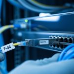
Consider a national retail chain deploying edge computing nodes in 120 stores. Each store runs a local compute cluster with a 10G uplink to a regional aggregation switch, using SFP+ SR optics on 300 m MMF runs with LC connectors. During high-demand promotions, the site backhaul carries bursty video analytics and POS telemetry, pushing sustained utilization above 70% for hours.
In the first phase, the team upgrades selected stores to 25G to reduce congestion. They keep the same fiber routes but replace optics to SFP28 25G SR when the plant is confirmed as OM4 with measured attenuation consistent with the optics’ reach class. For stores with older fiber or uncertain patch panel losses, they standardize on 25G LR over SMF to avoid marginal MMF performance. The key operational win is that DOM telemetry is used to trigger pre-fail events when Rx power drifts, letting technicians schedule cleaning and replacement during low-risk windows.
By the second phase, they introduce a site failover design: if the primary uplink degrades, traffic shifts to a secondary path that uses different optics and sometimes different fiber. That is why transceiver selection must include not only the active path but also the failover behavior, including expected Rx power and switch port speed negotiation.

Common pitfalls and troubleshooting tips that prevent edge outages
Even experienced teams get tripped up during transceiver selection because the failure modes are subtle. Below are concrete pitfalls I have seen in the field, with root cause and a practical solution.
Link comes up intermittently, then drops under load
Root cause: marginal link budget combined with thermal effects or connector contamination. The link may pass initial tests but fail when the transmitter warms up or when the site experiences vibration and micro-movements in patch cords.
Solution: clean LC/MPO connectors with approved lint-free methods, re-seat transceivers, and verify Rx optical power against the vendor’s acceptable operating range. Measure and record DOM Tx/Rx power immediately after installation and during the first maintenance window.
“Unsupported transceiver” messages or ports stay down
Root cause: switch platform enforces EEPROM vendor identifiers or expects a specific coding scheme. Some third-party optics work electrically but fail the platform’s compatibility checks.
Solution: confirm the optics are on the switch vendor’s tested list for that exact model and firmware revision. If you must use third-party modules, pre-validate them in a lab with the same switch model and software version before scaling deployment.
Wrong fiber type or wrong MMF grade assumptions
Root cause: using a 25G SR optic over MMF that is not the expected OM4/OM3 grade, or using patch cords that exceed the effective reach due to additional connectors and splices.
Solution: verify fiber grade with documentation and, ideally, with OTDR results or certified attenuation tests. Apply conservative reach margins and avoid assuming “it worked for 10G,” because higher speed optics are more sensitive to bandwidth and modal dispersion.
DOM telemetry missing or misleading in monitoring
Root cause: DOM fields differ across vendors, and some monitoring stacks assume standard names or thresholds. You might see zeros, stale readings, or incorrect units, leading to false alarms or missed warnings.
Solution: validate telemetry ingestion with a known-good module and confirm which DOM parameters are available. Set alerts based on observed Rx power drift rather than raw “threshold defaults” that may not match your optics.
When troubleshooting, keep a disciplined approach: isolate whether the issue is optics, fiber plant, switch configuration, or physical layer cleanliness. Swap transceivers between two known-good ports when possible, and only then start re-terminating fiber.

Cost, spares strategy, and ROI for edge transceiver selection
In edge computing, transceiver selection is as much a lifecycle cost decision as it is a technical one. OEM optics are often priced higher but may offer smoother compatibility and predictable DOM behavior. Third-party optics can reduce upfront cost, but you should budget time for validation and maintain a tighter spares and failure tracking process.
Typical street pricing varies widely by vendor, speed, and reach class. As a realistic planning range, many 10G SR SFP modules may fall into the low tens of dollars to low hundreds per unit depending on brand and warranty; 25G and 100G optics can be several times higher. The more important ROI lever is downtime reduction: one failed optics swap during an outage can cost more than the price difference, especially if a site is remote or access is limited.
TCO also includes power and thermal impact. Higher-power optics increase heat load in dense edge racks; over time, this can raise cooling costs or accelerate fan wear. If your environment is tight on airflow, choose optics with documented power draw and ensure your rack cooling profile is validated during peak demand.
FAQ
How do I choose between MMF SR and SMF LR for edge nodes?
Start with measured distance and your fiber plant grade. If you have verified OM4 and clean termination practices, MMF SR can be cost-effective for short runs; otherwise, SMF LR offers a more forgiving link budget and easier scaling for dynamic demand.
Will third-party transceivers work with my switch?
They often do, but compatibility depends on the switch model, firmware, and the optics’ EEPROM identifiers. Pre-validate in a lab using the same switch and software version, then standardize part numbers for field deployment.
What DOM features should I require for edge monitoring?
Require Tx power, Rx power, temperature, and voltage fields that your monitoring system can ingest reliably. Also confirm that the optics provide stable readings under temperature swings, and set drift-based alerts rather than relying only on static thresholds.
What is the minimum optical margin I should plan for?
A practical target is 3 to 6 dB beyond the vendor’s nominal reach, then adjust based on connector counts, splice quality, and whether the link will be touched during maintenance.
Why do links fail only during heat waves?
Thermal stress reduces transmitter output and can push the receiver near sensitivity limits. If link power margins are tight, heat waves reveal the weakness; fix by improving optical margin, validating airflow, and cleaning connectors.
How should I structure transceiver spares for remote edge sites?
Stock spares by site role and expected failover paths, not just the active uplink. Keep at least one spare per critical optics type and record DOM readings from installed modules to speed up field diagnosis.
If you want to operationalize this approach, start by mapping your edge fiber plant and switch port compatibility, then build a repeatable transceiver selection checklist for every new site. Next, review fiber link budget to ensure your link margins survive both normal load swings and maintenance activities.
Author bio: I have deployed and troubleshot routing and switching systems in multi-site edge environments, including fiber optics, VLAN segmentation, and VPN backhaul designs. I focus on measurable link budgets, DOM telemetry, and field-ready procedures that reduce downtime during upgrades.