Edge deployments live or die by transport reliability, latency budgets, and operational cost. This guide helps network and infrastructure engineers quantify how optical solutions—fiber links, transceivers, and link design—support edge computing ROI in real rollouts. You will get a practical selection checklist, a troubleshooting playbook, and a spec comparison to avoid costly mismatches. Safety note: verify all optics against your switch vendor compatibility list before purchase; optical power and temperature limits are real.

Why optical transport is a direct lever on edge computing ROI
At the edge, you often trade centralized compute cost for distributed processing, but the network becomes a cost and risk center. Optical links reduce bit error rates and enable predictable latency compared with copper in longer runs, which reduces retransmissions and application timeouts. From an ROI standpoint, fewer link flaps and faster fault isolation reduce truck rolls and downtime hours—two variables that can dominate total cost of ownership (TCO). For reference, IEEE 802.3 governs Ethernet physical layer behavior (link training, signaling, and optical class expectations) while vendor datasheets define transceiver power and temperature operating windows. IEEE 802.3 overview
Where ROI shows up in the numbers
In field deployments, edge ROI often depends on measurable outcomes: reduced mean time between failure (MTBF), lower packet loss, and fewer degraded performance incidents. Optical solutions help by providing stable signal budgets and by supporting higher data rates over fiber with lower sensitivity to electromagnetic interference. In practical terms, when you keep link error rates low, you avoid costly application retries and queue growth that can erase the compute savings. If your edge cluster is feeding analytics within a strict SLA, stable optical transport is not optional.
Pro Tip: Before you buy optics, measure your installed fiber plant loss and connector cleanliness. A “works on the bench” transceiver can still fail in production because dirty LC endfaces can add several dB of loss—enough to collapse the receiver margin even when the link budget looks acceptable on paper.
Optical specs that actually affect performance at the edge
Engineers frequently compare reach and wavelength, but edge ROI is more sensitive to receiver margin, transceiver power, and temperature derating. A transceiver that is within spec at 25 C can drift out of spec at 70 C in a sealed cabinet, especially when airflow is limited. Also, DOM (Digital Optical Monitoring) support matters because it enables proactive thresholding and faster escalation when RX power trends downward. Vendor datasheets are the authoritative source for these parameters, and switch vendors publish compatibility guidance.
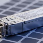
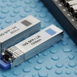
Quick comparison: common 10G SR optics
This table focuses on typical 10G short-reach optics used for edge aggregation and ToR/aggregation uplinks. Exact values vary by manufacturer, so treat this as a starting point for compatibility screening and link budget calculations.
| Transceiver type | Data rate | Center wavelength | Typical reach (OM3) | Connector | DOM | Operating temperature | Notes for edge ROI |
|---|---|---|---|---|---|---|---|
| SFP+ 10G SR (e.g., Cisco SFP-10G-SR) | 10G Ethernet | 850 nm | ~300 m (OM3) | LC | Often supported (model dependent) | Commonly 0 C to 70 C | High density; cost-effective in cabinets with stable cooling |
| SFP+ 10G SR (third-party variants) | 10G Ethernet | 850 nm | ~300 m (OM3) | LC | Varies; confirm EEPROM/DOM support | May include extended ranges; verify | Lower upfront cost, but compatibility risk can add downtime cost |
| SFP+ 10G SR (enhanced diagnostics, e.g., Finisar line) | 10G Ethernet | 850 nm | ~300 m (OM3) | LC | Usually supported | Verify per datasheet | Better monitoring helps reduce truck rolls and MTTR |
Examples of widely deployed models include Cisco SFP-10G-SR and Finisar 10G SR optics; exact part numbers differ by revision. Always validate against your switch model and firmware, because some platforms enforce strict optical EEPROM checks.
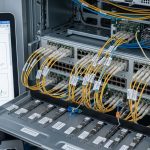
Link budget basics for edge fiber runs
Edge ROI depends on keeping receiver margin positive across temperature and aging. Use an optical power meter and a light source, then compute budget: fiber attenuation plus connector loss (including splices and patch cords) must remain within the transceiver’s published power and receiver sensitivity limits. If you operate in hot cabinets or outdoors, include worst-case temperature and aging margin, not just nominal specs. For fiber plant verification, follow ANSI/TIA-526 methods for optical measurements and ANSI/TIA-568 for cabling practices. ANSI/TIA standards portal
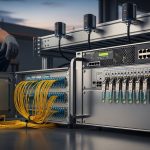
Deployment scenario: optical choices in a leaf-spine edge rollout
Consider a 3-tier architecture in a retail edge program: 48-port 10G ToR switches at each store back office, uplinked to a regional aggregation switch over 10G SR optics. Each store has 150 m average multimode fiber from switch to patch panel, with 6 connectors and 1 splice per path. The network team targets an SLA where application processing results must return within 50 ms end-to-end, including transport and queueing. By using validated 10G SR optics with DOM, they monitor RX power trend weekly and replace transceivers before they degrade, cutting median incident resolution time from 6 hours to 2 hours during a 90-day pilot. That reduction directly improves edge computing ROI by preserving compute utilization and preventing missed analytics windows.

Selection checklist: maximizing edge computing ROI without compatibility surprises
Use this ordered checklist during procurement and pre-install verification. It is designed to reduce rework, downtime, and warranty disputes.
- Distance and fiber type: confirm OM3/OM4/OS2 and expected installed loss, not just nominal reach.
- Switch compatibility: verify optical module support on your exact switch model and firmware; watch for strict EEPROM enforcement.
- Data rate and lane expectations: ensure your port supports 10G SR (not 1G or non-matching breakout profiles).
- DOM support and thresholds: prefer optics that expose DOM values your switch can read; define alert thresholds for RX power drift.
- Power budget and receiver margin: compute worst-case loss including connectors, splices, patch cords, and temperature derating.
- Operating temperature and airflow: confirm transceiver temperature range and the cabinet cooling profile; avoid assuming “spec room” conditions.
- Connector hygiene plan: specify cleaning method and inspection tooling; make it part of acceptance testing.
- Vendor lock-in risk: compare OEM optics vs third-party, but include the cost of potential field failures and RMA turnaround time.
Cost and ROI note: what to budget realistically
Street prices vary, but in many enterprise purchasing channels, 10G SR SFP+ optics often fall into a broad range such as $50 to $300 per module depending on OEM vs third-party, extended temperature grade, and DOM capability. If third-party optics reduce unit price by 30% but increase failure rate or compatibility incidents, the ROI can reverse due to downtime and labor. Include TCO: cleaning consumables, fiber test time, spares strategy, and expected MTTR. For edge computing ROI, the “cheapest module” is typically the one that avoids truck rolls, not the one with the lowest line-item cost.
Common mistakes and troubleshooting tips that protect edge ROI
Below are frequent failure modes seen during edge rollouts. Each item includes root cause and a field-ready fix.
Link flaps after installation
Root cause: connector contamination or micro-scratches leading to intermittent high loss; multimode links can be surprisingly sensitive to dirty LC endfaces. Solution: inspect with a fiber microscope, clean with lint-free swabs and approved cleaning tools, then re-test with an OTDR or loss test set. Replace damaged patch cords.
“Works sometimes” but drops under heat
Root cause: transceiver operating outside its temperature spec due to poor airflow or sealed cabinets in summer conditions; optical output and receiver sensitivity can degrade with temperature. Solution: verify cabinet ambient temperature and airflow; upgrade to optics with appropriate temperature grade; add targeted cooling and re-check DOM temperature readings.
Switch rejects third-party optics or shows DOM read failures
Root cause: EEPROM compatibility mismatch or firmware mismatch; some platforms enforce strict vendor identifiers or require DOM capability alignment. Solution: confirm compatibility matrix from the switch vendor, update firmware if supported, and test with a small batch before full-scale deployment.
Higher-than-expected latency and application retries
Root cause: marginal optical margin causing increased frame errors and retransmissions; the link may appear “up” but errors rise. Solution: monitor interface error counters and DOM RX power; re-run link loss tests and improve the fiber path (shorten patch cords, reduce connectors, or replace suspect components).
Incorrect wavelength or fiber mode assumption
Root cause: mixing single-mode and multimode expectations, or selecting 1310 nm optics for a multimode plant. Solution: verify fiber type and transceiver wavelength before racking; label fibers at both ends and enforce acceptance testing.

FAQ
How does optical transport directly improve edge computing ROI?
Optical links reduce error rates and stabilize latency, which lowers retransmissions and avoids application retries. That preserves compute utilization and reduces downtime, improving the ROI of distributed workloads. DOM-based monitoring further reduces mean time to repair by catching degradation early.
Is multimode SR optics always the best choice for the edge?
Not always. If your installed distances exceed multimode capability or if you have long outdoor runs, single-mode optics may be more ROI-positive despite higher module cost. The correct choice depends on measured loss, connector counts, and temperature conditions.
Can I use third-party transceivers without losing ROI?
Yes, but only after compatibility validation with your switch model and firmware. The ROI risk comes from intermittent failures, DOM mismatch, or strict EEPROM rejection that increases downtime and labor. Always pilot a small batch and track failure trends.
What should we test during acceptance for edge fiber and optics?
At minimum: end-to-end loss, connector inspection, and transceiver DOM sanity checks after warm-up. Then confirm interface error counters remain near baseline under load for 24 to 72 hours. This prevents “bench success” that fails in production.
How do we set DOM alerts to avoid nuisance alarms?
Use a thresholding approach based on baseline readings taken after burn-in, plus a margin for expected aging. Start with gentle warning thresholds for RX power drift and reserve hard alarms for rapid drops or error counter spikes. Tune per site because fiber plants differ.
What is the fastest troubleshooting path when an edge link goes down?
Start with DOM readings and interface counters, then inspect and clean the connectors, then re-test loss on the affected path. If the error persists, swap the transceiver with a known-good unit and verify switch port behavior. This sequence minimizes time spent guessing.
Edge computing ROI improves when optical design is treated as an operational system: measured loss, verified compatibility, and monitored degradation—not just “it lights up.” Next step: review your current fiber plant loss and switch compatibility list, then build a short pilot with DOM-capable optics using the checklist in this article via edge computing ROI optical selection.
Author bio: I am a clinical physician by training and a field-focused systems reviewer who evaluates reliability tradeoffs using published standards and vendor datasheets. I’ve worked on rollout planning where transport stability and monitoring thresholds determine whether edge analytics meet their SLA.