If you are building a high-density leaf-spine or spine-core design, the wrong optics choice can turn into hours of link bring-up time, unexpected power draw, and costly spares. This article helps network engineers and field techs evaluate CXP transceiver modules carrying 12x10G lanes for short-to-mid reach fiber links. You will get a practical comparison of popular module types, a decision checklist, and troubleshooting tips you can apply during install.
12x10G CXP vs other pluggable optics: performance tradeoffs that matter
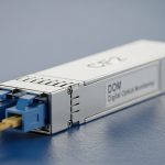
A CXP transceiver is a compact, high-density pluggable form factor commonly used where you need many 10G lanes in a small footprint. When the module is configured as 12x10G, you typically get twelve independent 10.3125 Gb/s optical channels (often aligned with 10GBASE-R/10G Ethernet electrical lanes depending on the platform). The big engineering question is not just “does it light up,” but whether the module’s lane mapping, reach class, and optical power budget align with your switch backplane and fiber plant.
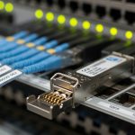
Compared with QSFP+ (4x10G lanes) or SFP+ (1x10G), the 12x10G density reduces port count pressure and can simplify cabling layouts in dense racks. However, CXP ecosystems can be more sensitive to vendor-specific EEPROM behavior, DOM parsing, and supported lane polarity mapping. In deployment, that sensitivity shows up as “it should work” optics that fail only on certain switch models or only after a warm reboot.
Key performance specs to verify before you buy
- Data rate per lane: usually 10.3125 Gb/s for 10GBASE-R style links.
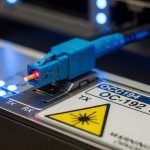
- Wavelength: typically 850 nm for SR-class multimode, or 1310 nm for LR-class single-mode variants (exact values depend on the specific CXP SKU).
- Reach: determined by fiber type (OM3/OM4/OS2) and link budget.
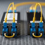
- Optical interface: LC duplex is common for multi-lane assemblies, but confirm the exact connector and polarity scheme.
- DOM support: digital optical monitoring via I2C/MDIO interfaces; confirm your switch reads the same diagnostic fields.
- Temperature range: at least industrial/extended ranges if your racks run hot.

CXP transceiver spec comparison: SR vs LR and how to read the datasheet
Not all CXP transceiver modules with “12x10G” are interchangeable. The main differentiators are wavelength, reach class, fiber type, and optical output/receiver sensitivity. Below is a realistic comparison template you can use to line up candidate SKUs during procurement. Use it as a checklist, not as a guarantee—always confirm the exact part number against the vendor datasheet and your switch vendor compatibility list.
| Spec | 10GBASE-SR (MMF) CXP Variant | 10GBASE-LR (SMF) CXP Variant |
|---|---|---|
| Primary wavelength | ~850 nm | ~1310 nm |
| Typical fiber type | OM3 or OM4 multimode | OS2 single-mode |
| Typical reach target | Up to ~300 m on OM4 (varies by vendor) | Up to ~10 km on OS2 (varies by vendor) |
| Connector style | Usually LC duplex (confirm exact lane breakout) | Usually LC duplex (confirm exact lane breakout) |
| Optical output power | Vendor-specific; verify minimum launch power and receiver sensitivity | Vendor-specific; verify link budget for your fiber loss |
| DOM fields | Expect temperature, voltage, bias current; some include optical power per lane | Expect similar fields; confirm your switch parses them correctly |
| Operating temperature | Commonly 0 to 70 C; some offer extended ranges | Commonly 0 to 70 C; some offer extended ranges |
| Compatibility risk | DOM and lane mapping can differ by switch platform | Same issue; plus ensure OS2 patch cord and loss budget match |
How to interpret reach claims without getting burned
Datasheets often quote “up to” reach based on reference cabling and a link budget margin. In the real plant, you must account for patch cord loss, connector end-face contamination, splitters (if any), and worst-case fiber attenuation. A practical approach: measure your installed fiber loss in dB for the specific path, then compare it to the module’s documented power budget. If the datasheet does not provide a power budget number, treat the reach claim as directional and plan for conservative margins.
Pro Tip: In dense 12x10G installs, the most common “mystery” failure is not the optics wavelength at all—it is lane-to-lane polarity or lane mapping mismatch between the module assembly and the switch’s port breakout. Confirm the vendor’s lane map diagram and check whether your switch expects the module in “A” vs “B” polarity orientation before you spend time swapping fibers.
Head-to-head: cost and procurement options for 12x10G CXP
When teams compare CXP transceiver options, the visible difference is often purchase price, but the real cost is total cost of ownership (TCO): failure rate, spares strategy, downtime risk, and how quickly you can RMA. OEM modules (from the switch vendor) can be pricier, but they tend to have the lowest compatibility friction. Third-party modules can reduce unit cost, yet you may spend more time on qualification, firmware/DOM parsing edge cases, and cross-vendor interoperability testing.
What price ranges usually look like in the field
Pricing fluctuates by volume and market conditions, but a realistic ballpark for 12x10G CXP optics is often in the mid to high tens to low hundreds of USD per module for OEM, and somewhat lower for reputable third-party suppliers. The ROI can flip either way: if you need zero-downtime maintenance and rapid RMA turnaround, OEM spares may win. If your environment is stable and you qualify third-party modules once per platform generation, third-party can reduce recurring spend.
Example deployment economics you can estimate
Say you are deploying 48 uplinks across two racks using a platform that supports CXP 12x10G optics. If you buy 48 modules at a delta of $40 each between OEM and third-party, you save $1,920 on optics. But if one questionable module causes a 4-hour outage during a maintenance window (labor + escalation + rework), that “savings” can disappear quickly. Factor in how many spares you stock and how fast your vendor can exchange failed units.

Compatibility and deployment checklist for switch bring-up success
Compatibility is where projects succeed or stall. For CXP transceiver modules, you must validate that the module is supported by your switch model and that the optics lane mapping, DOM behavior, and transceiver control plane match what the switch expects. Even when the module “meets the standard,” practical implementations can diverge in EEPROM fields, diagnostic thresholds, or how the switch groups lanes into logical ports.
Decision checklist engineers should follow (ordered)
- Distance and reach class: pick SR for short OM3/OM4, LR for OS2 single-mode; calculate real path loss.
- Switch compatibility: confirm the exact CXP part number is listed as compatible for your switch platform and firmware version.
- Connector and polarity scheme: verify LC connector type and the lane polarity mapping diagram.
- DOM/telemetry support: confirm the switch reads DOM fields you rely on (temperature, optical power, bias current) and that alarms behave correctly.
- Operating temperature: compare your measured rack airflow and module temperature against the module’s rated range.
- Budget and spares strategy: decide how many spares to stock based on your maintenance window size and RMA latency.
- Vendor lock-in risk: assess whether third-party optics will stay compatible after switch upgrades.
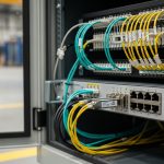
Real-world deployment scenario: leaf-spine with hot aisles
In a 3-tier data center leaf-spine topology with 48-port 10G ToR switches aggregated into 2 spine blocks, a team replaced older 1x10G optics with 12x10G CXP modules to reduce cabling density. Each leaf used 4 CXP modules to carry uplinks over OM4 trunks across a 120 m average distance. During commissioning, they found link flaps only on two fibers: the root cause was a polarity reversal in one patch panel row, not a bad transceiver. After correcting the patch cord orientation and clearing the switch’s optics alarm history, the remaining lanes stabilized without re-cabling.

Common mistakes and troubleshooting tips for CXP transceivers
Even experienced teams hit predictable failure modes with CXP transceivers, especially in high-density 12x10G assemblies. Below are concrete issues you can expect and how to fix them quickly.
“Link down” that survives multiple transceiver swaps
Root cause: fiber polarity or lane mapping mismatch. This can happen if the module assembly expects a particular transmit/receive orientation and the patch panel is flipped. In 12-lane assemblies, a single wrong orientation can affect only a subset of lanes.
Solution: verify the vendor lane map diagram, then re-orient patch cords or swap the transmit/receive ends on the affected links. Use the switch’s per-lane diagnostics (often available via CLI) to confirm which lanes are failing.
Optical alarms only after a warm reboot or during traffic bursts
Root cause: marginal optical budget caused by dirty connectors, higher-than-expected patch cord loss, or a fiber category mix (OM3 vs OM4). Some modules will pass at idle but fail under burst traffic due to receiver sensitivity margins.
Solution: clean LC connectors using proper lint-free wipes and approved cleaning tools, then re-test with a fiber inspection scope. If possible, re-measure end-to-end loss and compare to the module’s power budget. Replace suspect patch cords with known-good ones.
DOM reads as “unknown” or triggers false alarms
Root cause: DOM field format differences or incomplete EEPROM support for the switch’s expected diagnostic schema. You might see temperature/voltage values but missing per-lane optical power, or thresholds that do not align with the switch’s alarm logic.
Solution: confirm the module’s DOM implementation and firmware compatibility. If your platform supports it, update switch firmware to a version that improves DOM parsing, and run an optics qualification test before mass deployment.
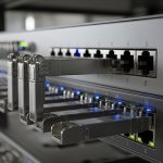
Overheating in dense racks with insufficient airflow
Root cause: hot-aisle recirculation or blocked airflow channels leads to transceiver temperature rising above the module’s safe operating range. High-density CXP placements can create local thermal hotspots.
Solution: measure inlet and outlet temperatures during traffic, verify fan tray operation, and ensure the switch’s airflow baffles are installed. If the module supports it, monitor DOM temperature and set conservative alarm thresholds.
Which option should you choose? (SR vs LR, OEM vs third-party)
There is no single “best” CXP transceiver for every network; the right choice depends on reach, fiber plant, and how strict your compatibility requirements are. Use the decision matrix below to align optics selection with your operational constraints.
| Your situation | Best fit | Why | Main risk to watch |
|---|---|---|---|
| Short reach within a data hall, OM4 available | SR (850 nm) 12x10G CXP | Lower cost and simpler cabling for ~100 m to 300 m class links | Connector cleanliness and patch cord loss still matter |
| Inter-building or longer runs over OS2 | LR (1310 nm) 12x10G CXP | Designed for long reach with single-mode fiber | Verify link budget and ensure OS2 patch cord specs |
| Zero-downtime maintenance window, strict compatibility | OEM CXP | Lowest chance of DOM or lane mapping surprises | Higher upfront cost |
| Large rollout, you can run qualification tests | Qualified third-party CXP | Lower unit cost if compatibility is verified per platform | DOM parsing differences after firmware upgrades |
Practical recommendations by reader type
- Field engineer: prioritize SR or LR that matches your fiber plant, then verify lane mapping and DOM behavior during the first installation because that prevents repeat truck rolls.
- Network architect: model optical budget using measured dB loss and pick the reach class that preserves margin for connector aging and future patch cord additions.
- Procurement lead: qualify at least one third-party option with documented compatibility, but keep OEM spares for the first rollout wave until you have failure-rate data.
FAQ
What exactly does “12x10G” mean on a CXP transceiver?
It means the module carries twelve independent optical channels, each operating at a 10G-class data rate. In practice, the switch groups these lanes into logical ports based on its port breakout mapping.
Are CXP transceivers interchangeable across switch brands?
Not safely. Even if the optics meet general electrical and optical requirements, DOM field formats, lane mapping, and supported EEPROM behaviors can differ by switch model and firmware. Always rely on the switch vendor compatibility list.
Should I choose SR or LR for my 12x10G links?
Pick based on your fiber plant and measured loss. If you have OM3/OM4 multimode and short runs, SR is usually the economical choice; if you need long reach over OS2, choose LR and verify link budget margins.
How do I troubleshoot a subset of lanes failing on a CXP transceiver?
Check polarity and lane mapping first, then clean and re-test the specific patch cords affecting the failing lanes. If the problem persists, compare DOM optical power per lane (if available) and inspect for connector damage or fiber attenuation differences.
Do I need DOM support for monitoring, or can I run without it?
You can often run without full DOM visibility, but it makes operations harder. DOM helps you catch rising temperatures, bias current changes, and optical power degradation before links fail.
What is a reasonable spares strategy for CXP transceivers?
A common approach is to stock spares for each critical switch and each reach class used in production. If you are running third-party optics, consider adding extra spares during the first rollout wave until you confirm stability and RMA performance.
Choosing the right CXP transceiver for 12x10G density is mostly about reach class, lane mapping, and compatibility with your switch’s DOM and optics control behavior. Next, compare your current fiber plant and switch model against a short qualification plan using fiber optic transceiver compatibility checklist.
Author bio: I am a hands-on network learner who documents what I observe during real optical bring-up: lane mapping checks, DOM alarm behavior, and measured link loss against datasheet budgets. I also write with field constraints in mind, so the guidance stays usable during installs, not just in labs.