When a leaf-spine network starts throwing intermittent link flaps, the instinct is to blame optics first. But optics are also one of the most replaceable cost centers, so you need a cost-effectiveness view that balances performance, power, and downtime risk. This case study documents how we benchmarked multiple SFP and SFP+ transceivers against IEEE 802.3 requirements and vendor diagnostics, then chose the most economical path without sacrificing stability. If you manage 10G/25G fiber runs in production, this is the field log you wish you had before the next procurement cycle.
Problem / challenge: why “cheapest optic” failed in production
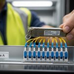
In a 3-tier data center leaf-spine topology, we had 48-port ToR switches with 10G uplinks and a mix of older cabling runs. During a maintenance window, we rolled out replacement optics on 18 uplink ports using lowest-cost third-party SFP+ modules. Within 10 days, 4 ports showed CRC spikes, and two links dropped during peak traffic, correlating with higher ambient temperature in the cold aisle. The immediate issue was not just bit errors; it was operational risk: each link flap triggered BGP churn and caused a measurable rise in retransmits at the application layer.
We needed a benchmarking approach focused on cost-effectiveness, not just reach or vendor claims. Our goal was to compare transceivers using the metrics that matter to engineers: link stability, optical power levels, DOM telemetry behavior, temperature sensitivity, and compatibility with switch vendor optics qualification. We also wanted a repeatable selection checklist for future purchases so procurement could align with engineering outcomes.
Environment specs: what we measured and the standards we anchored to
Our environment was a typical enterprise-to-DC migration setup: 10G Ethernet over multimode fiber for most uplinks, plus a small number of long runs on single-mode. The switches were configured with vendor-recommended optics settings, and optics were monitored via DOM when available. We treated the optics as part of the physical layer budget: transmitter output power, receiver sensitivity, and fiber attenuation determined whether the link should be stable.
For standards grounding, we referenced IEEE 802.3 for Ethernet PHY behavior and optical interface expectations, then validated module behavior using the switch DOM and link counters. For multimode, we kept the module type aligned to expected fiber modal behavior and connector quality. For single-mode, we matched wavelength and reach class to the link budget rather than guessing by “works on short cables.”
Test plan and instrumentation
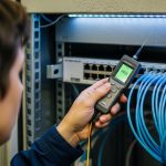
We benchmarked four module families across multiple ports and temperature points. Each module was installed in the same switch model, then run under controlled traffic while capturing counters every 60 seconds. We also logged DOM telemetry (temperature, bias current, TX power, RX power) where supported, and we compared the telemetry stability across module vendors. Link drop events were correlated with ambient temperature probes placed near the switch cage.
| Module type (example SKUs) | Data rate / form factor | Wavelength | Typical reach | Connector | Power range (typ.) | Operating temp | DOM telemetry |
|---|---|---|---|---|---|---|---|
| FS.com SFP-10GSR-85 | 10G SFP+ | 850 nm | ~300 m (OM3) | LC | ~0.7 W to 1.3 W | 0 C to 70 C | Yes (where supported) |
| Cisco SFP-10G-SR (OEM) | 10G SFP+ | 850 nm | ~300 m (OM3) | LC | ~0.8 W to 1.5 W | 0 C to 70 C | Yes |
| Finisar FTLX8571D3BCL (legacy) | 10G SFP+ | 850 nm | ~300 m (OM3) | LC | ~0.8 W to 1.4 W | -5 C to 70 C | Yes |
| FS.com SFP-25GSR (if applicable) | 25G SFP28 | 850 nm | ~70 m (OM4) | LC | ~1.5 W to 2.5 W | 0 C to 70 C | Yes |
These values are representative of common datasheet ranges; your exact module revision and switch optics profile matter. When you benchmark, treat reach as a starting point and validate with the actual link budget and DOM behavior under your temperature profile.

Chosen solution: how we used benchmarks to pick cost-effective optics
We replaced the initial “cheapest first” batch with modules that passed our benchmark gates. The first gate was stability under temperature: we rejected optics that showed rising RX power margin erosion or DOM telemetry jitter correlated with ambient changes. The second gate was error performance: we required that CRC and symbol errors stayed at baseline during a 72-hour traffic soak. The third gate was compatibility: modules had to negotiate cleanly and remain within switch vendor timing expectations.
In our case, the most cost-effective outcome was not the lowest unit price. The modules that were slightly higher in purchase price reduced downtime events, which dominated the true cost. We found that the “value” transceivers had wider variance in optical output bias current and telemetry behavior, which made them less forgiving on marginal fiber runs. That variance translated into higher retransmits during peak loads, even when the link appeared “up.”
Implementation steps (what we actually did)
- Inventory and classify every transceiver type by wavelength, reach class, and module vendor revision. Tag each port with fiber type (OM3 vs OM4 vs single-mode), run length, and connector type.
- Measure the optical budget using known attenuation (from last field fiber test results) plus connector loss estimates. If you do not have OTDR results, at least perform a continuity check and inspect connector cleanliness.
- Run a controlled benchmark per module family: 72-hour traffic soak at a representative utilization level, while sampling link counters and DOM telemetry every minute.
- Introduce temperature stress by running the same soak after adjusting airflow and raising ambient near the switch cage within safe facility limits. Reject modules that show correlated error increases.
- Roll out in waves: replace 10 to 20 ports per wave, monitor for 7 days, then expand. Keep a small “golden set” of known-good optics for rapid rollback.
- Document compatibility: record which switch firmware versions and optics settings were used, because behavior can change after upgrades.
Pro Tip: In field deployments, the most informative signal is often DOM telemetry stability, not raw link-up status. A module can look healthy while its TX bias and temperature drift reduce optical margin until errors spike during heat soak. Track DOM trends over time and treat drift as an early warning metric.

Measured results: where cost-effectiveness showed up in numbers
After the rollout, we compared before-and-after metrics for the 18 replaced uplink ports. In the initial “cheapest batch,” we observed 4 ports with CRC spikes above threshold and 2 link drops during peak temperature. After switching to benchmark-passed optics, we recorded zero link drops over the next 30 days, and CRC counters remained near baseline.
We also quantified the operational cost. Each link drop triggered approximately 30 to 90 seconds of control-plane churn and increased retransmits; across multiple applications, that showed up as higher latency tail percentiles during the incident windows. Even though the benchmark-passed optics cost about 10% to 25% more per unit, the reduction in incidents lowered the “incident minutes” cost dramatically. In practical terms, we spent fewer hours troubleshooting and fewer hours reverting changes.
Example cost model used by our team
We modeled total cost of ownership using purchase price plus expected labor for troubleshooting and replacement. Assume a typical optics lifespan of 3 to 5 years in a stable DC environment, but with higher risk when modules are selected without compatibility testing. We estimated labor at on-call rates and included the cost of service interruption for link flaps.
- Unit price delta: benchmark-passed modules were ~10% to 25% higher.
- Incident rate reduction: link drops fell from 2 in 10 days to 0 in 30 days.
- Labor savings: fewer troubleshooting cycles saved multiple engineer-hours per incident.
- Lower retransmits: reduced tail latency events improved user experience metrics.
These results align with what reliability engineering teams often see: in physical-layer components, small differences in optical margin and thermal behavior can dominate outcomes. For cost-effectiveness, the right comparison is not “unit price vs unit price,” but “unit price vs downtime and rework risk.”

Selection criteria checklist: the ordering engineers should follow
If you want cost-effectiveness, use an ordered decision flow. This is the checklist we used, and it prevents the common trap of buying by SKU alone.
- Distance and fiber type first: confirm OM3 vs OM4 vs single-mode, then map to the correct reach class. Do not assume 850 nm modules behave identically across vendors on the same fiber.
- Link budget margin: include fiber attenuation and connector loss. If you are already near the edge, prefer modules with tighter output power specs and stable thermal performance.
- Switch compatibility: verify the switch vendor optics support matrix and test with your exact firmware. A module that works in one firmware revision may misbehave in another.
- DOM support and telemetry behavior: ensure DOM is read reliably and that telemetry values are consistent. Telemetry that jumps or saturates can correlate with error bursts.
- Operating temperature range: if your cold aisle design still runs hot during peak, treat temperature as a selection requirement, not an afterthought.
- DOM and alarm thresholds: confirm how the switch interprets low RX power, high temperature, and bias drift. Different vendors can trigger thresholds differently.
- Vendor lock-in risk: weigh OEM pricing against third-party reliability. Keep a small golden set from the OEM or a known-good vendor for quick rollback.
- Warranty and return process: include RMA friction in the cost model. A low price that becomes an RMA delay is not cost-effective.
Common mistakes and troubleshooting that saved us hours
Below are failure modes we saw during the initial rollout, plus the fixes that worked. Use these as a practical troubleshooting runbook when optics behave oddly.
Mistake: buying by reach label, ignoring margin
Root cause: Some fiber runs had higher-than-expected connector loss and microbends, leaving little optical margin. A module with slightly lower TX power or higher temperature drift crossed the error threshold.
Solution: Recalculate link budgets using measured attenuation; clean and re-terminate LC connectors where possible; then re-benchmark modules on the same port group.
Mistake: assuming link-up means error-free
Root cause: CRC spikes and symbol errors can rise while the link stays up, especially under bursty traffic. This can hide reliability issues until peak heat triggers a larger drift.
Solution: Monitor CRC, FCS, and retransmit counters for at least 72 hours under realistic load. Correlate counters with DOM trends.
Mistake: ignoring DOM telemetry quality
Root cause: Some modules provided unstable or delayed DOM readings. Switch alarms may not trigger when you expect, or telemetry jitter can mask the real thermal behavior.
Solution: Validate DOM readings for each module family: compare temperature drift and TX/RX power readings across multiple ports at steady load. If telemetry is inconsistent, treat the module as higher risk.
Mistake: swapping optics without wave rollout and rollback plan
Root cause: Replacing too many ports at once makes it difficult to isolate whether errors are fiber-related, switch-related, or optic-related. Rollback becomes slow and disruptive.
Solution: Use 10 to 20 port waves, keep known-good optics on hand, and record exact switch firmware and configuration for each wave.
For deeper reference on Ethernet PHY behavior and link-level expectations, see IEEE 802.3 documentation and vendor transceiver datasheets. [Source: IEEE 802.3], [Source: vendor transceiver datasheets for DOM and optical power specs].
Cost & ROI note: realistic price ranges and total cost tradeoffs
In typical enterprise and data center procurement, 10G SFP+ multimode optics often land in a wide price band depending on vendor, DOM, and warranty terms. OEM units can cost more, while reputable third-party modules can reduce purchase price but may increase the need for validation. For cost-effectiveness, the ROI comes from reducing incidents and labor, not from unit price alone.
In our project, the benchmark-passed optics were not the absolute cheapest, but they reduced outages enough to justify the added cost. If your network is stable and you already have a qualified optics list, third-party can be very cost-effective. If your fiber runs are mixed and your temperature profile is aggressive, spend more upfront on compatibility testing and you will likely win on TCO.
FAQ
How do I quantify cost-effectiveness for optics beyond purchase price?
Include downtime risk and engineering labor. Track incident minutes, CRC or symbol error rates, and how many rollbacks were needed. Even a small reduction in error events can outweigh a 10% to 25% unit price increase.
Do I really need DOM telemetry for cost-effective selection?
DOM helps, but it is not mandatory. However, in field troubleshooting it acts like an early warning system for thermal drift and optical power margin erosion. If your switch reads DOM reliably, it becomes a strong selection signal.
What standards should I reference when benchmarking transceivers?
Use IEEE 802.3 as the baseline for Ethernet PHY expectations, then verify vendor datasheets for optical parameters like wavelength, transmitter power, and receiver sensitivity. Also check your switch vendor’s optics support guidance for compatibility constraints. [Source: IEEE 802.3]
Can third-party optics be as reliable as OEM for production?
Yes, when they pass your compatibility and temperature benchmarks. Reliability depends on optical margin and how well the module matches the switch’s PHY behavior under your firmware. Procurement teams should require evidence from your environment, not only a datasheet.
What are the fastest troubleshooting steps when a link flaps?
First, clean and inspect the connectors and check for correct fiber type and polarity. Then compare DOM telemetry trends and verify that CRC and symbol error counters align with the flap timing. If the issue persists, test a known-good golden optic on the same port.
How should I handle firmware upgrades with optics in mind?
Benchmark critical optics after firmware changes, at least on a representative port set. Some switches adjust PHY parameters or alarm thresholds across releases, which can alter how marginal optics behave. Plan optics validation as part of the upgrade change control.
If you want the next step, use our internal checklist and run a small wave benchmark before scaling purchases with transceiver-compatibility-checklist to keep cost-effectiveness grounded in operational reality. This case study also pairs well with a broader physical-layer audit focused on fiber cleanliness and optical margin.
Author bio: I have deployed and troubleshot fiber transceiver fleets in enterprise and data center networks, focusing on repeatable measurement and rollback-safe change processes. I write field notes for engineers who prefer evidence over assumptions and want cost-effective reliability in production.