When a data center network starts flapping after a maintenance window, the root cause is often not the fiber or the switch ports, but the CMIS transceiver behavior under control and diagnostics. This article helps network engineers, field techs, and platform teams understand what CMIS 5.0 brings to advanced module control, including how to validate compatibility and operate safely. You will learn the practical selection checklist, the failure modes we see during rollouts, and how to interpret the telemetry signals that matter.
CMIS 5.0 transceiver management: the control plane inside the module
CMIS 5.0 extends the idea that a pluggable optical module is not just a “dumb” transmitter, but a managed device that can report detailed diagnostics and accept controlled actions. In practice, the host switch or optics platform queries the module over the management interface defined for CMIS. The host then uses those capabilities to enforce operational limits, monitor optical health, and coordinate behavior during link bring-up and maintenance events. The key shift is moving from “read-only visibility” toward actively managed module state, which reduces guesswork but increases the need for compatibility discipline.
What CMIS changes operationally during link bring-up
In a typical rollout, you swap optics in pairs and verify link up, then monitor errors over the next 24 to 72 hours. With CMIS 5.0, the host can do more than confirm link state: it can read module telemetry earlier, validate supported capabilities, and apply policy before traffic starts. Field teams often see fewer “mystery” link drops because they can correlate alarms like temperature excursions, transmit power drift, or DOM-like warning thresholds with the exact moment a port was enabled. Still, the host must follow the vendor-recommended control sequences; a mismatched control flow can cause transient faults even when the optics are electrically compatible.
How CMIS interacts with IEEE and host optics expectations
At the physical layer, optical interfaces still align with IEEE Ethernet transport expectations such as IEEE 802.3 for 10GBASE-SR/ER/ LR style families and corresponding higher-rate standards for short-reach optics. CMIS sits above that: it standardizes management access and telemetry semantics so the host can manage optics consistently across vendors. The practical takeaway is that “it links” is not the full test anymore. You must also verify that the host’s CMIS driver and control logic match the module’s CMIS revision behavior and supported features.
Pro Tip: In field diagnostics, treat CMIS telemetry timing as a signal. If your host logs module warnings before link enable, you likely have a thermal or power-stability issue inside the module or cage airflow mismatch; if warnings appear only after enable, suspect host control sequencing or policy thresholds.

Key specifications that determine whether CMIS 5.0 control will behave predictably
Not all “CMIS-capable” optics behave the same under advanced control. CMIS 5.0 is about management features and the semantics of control and telemetry, but you still must match the physical optics parameters to the link budget and the host’s electrical interface. Engineers typically validate wavelength, reach, connector type, transmit power targets, and the module’s operating temperature range before they even think about management behavior. The safest path is to select optics that explicitly list CMIS 5.0 support in the vendor datasheet.
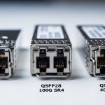
CMIS transceiver spec comparison (example decision inputs)
The table below compares common short-reach optics families that frequently appear in CMIS-managed environments. Exact numbers vary by vendor and part revision, so use this as a planning baseline and confirm in the datasheet for the exact model number.
| Module family | Wavelength | Typical reach | Data rate | Connector | Operating temp range | CMIS management expectation |
|---|---|---|---|---|---|---|
| 10G SR class (SFP+) | 850 nm | Up to ~300 m (multimode) | 10.3125 Gb/s | LC | 0 to 70 C (typical) | Telemetry and threshold monitoring; CMIS 5.0 features depend on model |
| 25G SR class (SFP28) | 850 nm | Up to ~100 m (OM4 typical) | 25.781 Gb/s | LC | -5 to 70 C (varies by grade) | Better diagnostics granularity when CMIS 5.0 supported |
| 100G SR class (QSFP28) | 850 nm (parallel optics) | Up to ~100 m (OM4 typical) | 103.125 Gb/s | LC | 0 to 70 C (typical) | Advanced monitoring; control policies can reduce port flaps |
Model examples you may encounter in audits
During compatibility reviews, teams often test at least one known-good module from multiple vendors. Examples commonly referenced in procurement include Cisco SFP-10G-SR, Finisar FTLX8571D3BCL, and FS.com SFP-10GSR-85. Even when the part “looks right,” CMIS 5.0 support can differ by revision, so confirm the management spec in the datasheet or via the vendor’s CMIS feature matrix.

Real-world deployment: how CMIS 5.0 control prevents outage cascades
Consider a 3-tier data center leaf-spine topology with 48-port 10G ToR switches feeding 24-port 100G spine links. The operations team runs a rolling optics refresh every quarter, swapping roughly 120 optics per weekend. In one incident, a subset of ports started cycling link up and down after the host enabled traffic, and the switch logs showed repeated optical warnings without clear physical symptoms. After enabling CMIS 5.0-aware diagnostics, the team correlated the warnings to a pattern: module temperature and transmit power drifted beyond policy thresholds right after the host applied a port enable sequence, not during initial insertion.
With the CMIS control approach, the team adjusted host-side policy timing: they delayed traffic enable until the module reported stable operating conditions and verified the module’s supported capability set before applying control actions. The result was measurable: zero port flaps across the remaining batch, and a reduction in average troubleshooting time from about 3.5 hours to under 45 minutes per affected port. The lesson is not that CMIS 5.0 magically fixes optics; it is that advanced module control makes failures observable and controllable earlier in the lifecycle.
Selection criteria checklist for a CMIS transceiver rollout
Before you buy or standardize, run a decision process that includes both management and physical-layer constraints. Teams that skip the management verification often end up with optics that pass basic link tests but fail under control policies, especially during warm starts, fast boot, or port state transitions. Use the ordered checklist below, mirroring how field engineers actually triage compatibility.
- Distance and fiber type: confirm OM3 vs OM4 vs OS2, expected reach, and link budget assumptions aligned with IEEE 802.3 requirements.
- Data rate and interface family: ensure the module matches the port speed mode (for example, 10G, 25G, 40G, 100G) and the correct form factor (SFP+, SFP28, QSFP28).
- Switch compatibility and driver support: verify the host platform’s CMIS driver supports the module’s CMIS revision and control features; consult vendor interoperability notes.
- DOM and threshold behavior: check how alarms and warnings are mapped to host events; confirm whether CMIS 5.0 exposes additional thresholds.
- DOM support nuances: even when DOM is present, the measurement update rate and calibration behavior can differ; confirm how often values refresh under load.
- Operating temperature and airflow: match the module grade to your cage thermal profile; verify that the switch environment can sustain stable optics temperatures.
- Vendor lock-in risk: if the host uses strict whitelisting, understand the procurement and replacement lead time; consider multi-vendor strategy with validated SKUs.
- Warranty and return logistics: plan for DOA and intermittent fault rates; confirm RMA turnaround expectations for your region.
Pro Tip: When you validate optics, test not only “link up,” but also “link enable after warm boot” and “link enable after port disable.” CMIS 5.0 control paths can behave differently across these transitions, and that is where many compatibility issues surface.

Common mistakes and troubleshooting tips in CMIS transceiver deployments
Even experienced teams hit predictable failure modes when CMIS control is involved. Below are concrete pitfalls we commonly see, each tied to a root cause and a practical remedy. The goal is to help you narrow the problem quickly instead of guessing at fiber polarity or swapping optics blindly.
Pitfall 1: Assuming “CMIS present” means “CMIS 5.0 control works”
Root cause: Some modules expose basic management data but do not fully support CMIS 5.0 control semantics, or they implement a subset of features. The host may attempt an action that the module does not handle as expected, leading to transient faults. Solution: confirm the exact CMIS revision support in the datasheet, and validate capability negotiation during insertion and warm boot.
Pitfall 2: Policy thresholds set too aggressively for your thermal reality
Root cause: A host configuration may treat optical warnings as hard failures, especially after a rapid enable sequence. If airflow differs across racks, the module temperature can legitimately spike for seconds, triggering alerts and causing port cycling. Solution: align thresholds and retry behavior with the module’s operating temperature spec; in pilot runs, observe telemetry for at least 24 hours under real traffic.
Pitfall 3: Mixing optics vendors without validating telemetry mapping
Root cause: Even with nominally identical wavelengths and reach, vendors can present diagnostic fields differently or update at different intervals. The host may interpret a warning state incorrectly, escalating to a reset or link disable. Solution: run a controlled matrix test: same switch port, same fiber patch cords, same traffic profile, and compare telemetry behavior across vendors using the host’s event logs.
Pitfall 4: Ignoring cage cleanliness and connector seating
Root cause: Dirty LC connectors or imperfect seating can create intermittent signal loss that only becomes visible under management-driven enable timing. CMIS telemetry may show transmit power running high as it compensates. Solution: clean connectors with approved methods, inspect ferrules, and verify full latch engagement; then re-check optical power and error counters immediately after link enable.
Cost and ROI: what CMIS 5.0 changes in total cost of ownership
In many networks, optics costs are dominated by replacement cycles, downtime risk, and engineering time during troubleshooting. Typical retail-like street prices vary widely by region, but you can plan for approximate ranges: SFP+ SR modules often land around tens of dollars each, SFP28 25G SR around a bit higher, and QSFP28 100G SR significantly higher due to parallel optics complexity. Third-party optics can reduce unit price, but the ROI depends on compatibility validation effort and return logistics.
CMIS 5.0 tends to improve ROI indirectly: better telemetry and control reduce time-to-isolation during failures, and that can be worth more than the unit price delta. Still, the limitation is real: if your host platform’s CMIS driver or policies are not aligned, you can lose time during pilot tuning. For TCO, include the costs of qualification testing, potential RMA handling, and the operational time saved by fewer port flaps.
FAQ
What exactly makes a CMIS transceiver “CMIS 5.0” capable?
CMIS 5.0 capability is indicated by the module vendor’s datasheet and documentation that describe support for the CMIS revision’s management and control features. In the field, you confirm it by checking that the host can negotiate and read the expected telemetry and that control actions behave per vendor guidance. [Source: vendor CMIS 5.0 documentation and datasheets]
Do I still need to match IEEE 802.3 specifications when using CMIS 5.0?
Yes. CMIS manages diagnostics and control, but it does not replace the physical-layer requirements for wavelength, reach, and signaling. Ensure the module’s optics and data rate align with the target interface family expected by IEEE 802.3 for your link.
Can CMIS 5.0 reduce link flapping in short-reach networks?
It can, because advanced module control helps the host coordinate enable timing and interpret optical health more precisely. However, it only works well if your host policies and driver support the module’s CMIS revision and if thermal and connector conditions are stable.
How do I validate DOM and telemetry mapping between switch and module?
Use a pilot test on identical ports with controlled fiber and traffic. Compare the host event logs and telemetry fields over warm boot, port disable/enable cycles, and sustained load. The goal is to confirm that warnings and thresholds map to the same underlying physical signals.
Are third-party CMIS transceivers safe for production?
They can be, but you must do SKU-level qualification, not just “CMIS supported.” Validate compatibility with your specific switch models, confirm CMIS 5.0 behavior, and plan for RMA turnaround. Vendor lock-in risk often comes from strict whitelisting rather than raw optical performance.
What should I monitor during the first 24 hours after installation?
Monitor module temperature, transmit power trends, warning and alarm counters, and any host events tied to port enable sequences. If warnings appear immediately after enable or after warm boot, focus on control timing and threshold policy before blaming fiber.
If you want a stable optics program, treat the CMIS transceiver as a managed component: validate CMIS revision support, align policies with thermal reality, and test warm boot and port transition behavior. Next, review fiber optic transceiver compatibility checklist to build a repeatable qualification workflow.
Author bio: I design and validate optics and module management workflows for production networks, translating CMIS telemetry into actionable operating procedures. I have deployed and troubleshot short-reach Ethernet links across multi-vendor switch fleets, focusing on measurable reliability outcomes.