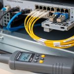
When an optical transport network upgrade stalls because the wrong transceiver lands in the wrong OTU slot, the outage cost is immediate and the rollback is slow. This article helps network engineers, field technicians, and procurement leads select the correct G.709 fiber module for OTU1, OTU2, and OTU4, with deployment-focused checks that prevent link bring-up failures. You will get a top-N field guide, a practical selection checklist, troubleshooting pitfalls, and a ranking table to support decisions under time pressure.
Top 1: OTU1 G.709 fiber module selection for legacy reach and cost control
OTU1 is commonly used in brownfield OTN overlays where operators want to upgrade transport without changing every optical layer at once. In practice, OTU1 transceivers often target ~2.5G line rates (depending on mapping and vendor implementation) and are selected for predictable reach on single-mode fiber (SMF) with mature 1310 nm or 1550 nm optics families. For bring-up, the most important variables are wavelength, connector type (typically LC), and whether the module supports the same OTN framing and FEC expectations as the far-end mux/demux.
Key specs and what to verify
Engineers usually validate: (1) optical nominal wavelength and type (for example 1310 nm vs 1550 nm), (2) reach budget versus fiber loss at the specific wavelength, (3) DOM availability for monitoring (laser bias current, received power, temperature), and (4) the OTU mode (OTU1) negotiated by the OTN shelf. Many operators run OTU1 over existing SMF plant where dispersion and attenuation are stable, but the penalty is lower throughput efficiency compared with OTU2/OTU4.
- Best-fit scenario: Upgrading a legacy aggregation layer while preserving existing fiber routing; small-to-medium bandwidth increments.
- Pros: Lower unit cost, widely available optics, easier interoperability with older OTN gear.
- Cons: Less capacity headroom; may become a bottleneck if traffic grows quickly.

Top 2: OTU2 G.709 fiber module for higher aggregation with manageable optics
OTU2 is a frequent “middle step” for networks that need more capacity but cannot jump directly to OTU4 everywhere. In many deployments, OTU2 is used to aggregate multiple tributary flows into a higher-rate OTN channel while keeping optical budgets within typical SMF operating ranges. Compared with OTU1, OTU2 modules impose stricter requirements on transmitter power stability and receiver sensitivity, so field checks should include DOM telemetry sanity ranges.
Operational details that matter in the field
For OTU2, technicians often see bring-up issues when the far-end expects a different OTU2 payload mapping mode or when the transceiver type differs (for example, different vendor families with distinct default FEC behavior). A practical approach is to confirm the OTU mode in the OTN shelf configuration, then validate that the transceiver line rate and optics class match the shelf profile before inserting the module into production.
- Best-fit scenario: 10G-to-OTN grooming where you need a step up from OTU1 capacity without redesigning the entire optical layer.
- Pros: Better capacity utilization than OTU1; often still compatible with common SMF reach classes.
- Cons: More sensitive to power budget and configuration mismatches than OTU1.
Top 3: OTU4 G.709 fiber module for backbone-grade capacity and tighter alignment
OTU4 is the backbone-grade option in many OTN designs, typically used where operators need substantial transport capacity per wavelength and want to reduce the number of parallel fibers. In the field, OTU4 transceivers demand careful handling: optics cleanliness, stable power budgets, and correct OTU4 framing are all critical because the system margin can be smaller than in lower OTU modes. If a network uses coherent or dense wavelength division multiplexing, OTU4 often sits at the center of the optical performance chain, so alignment and connector quality can dominate failures.
What to measure before you close the rack
Before finalizing a cutover, engineers should compare expected received power (from DOM or OTN shelf telemetry) against the vendor’s recommended operating range and confirm that alarms clear after stabilization. If you must reuse patch cords, inspect and clean LC ends with a microscope and verify polarity. OTU4 deployments also tend to show higher sensitivity to fiber plant issues such as micro-bends and dirty bulkhead adapters.
- Best-fit scenario: Leaf-spine or metro backbone aggregation where you need high capacity with fewer wavelengths and strict SLA targets.
- Pros: High capacity density; fewer parallel optics reduces rack and power footprint.
- Cons: Tighter margins; more troubleshooting effort when configuration or optics quality is off.

Top 4: Specs comparison table you can use for procurement and acceptance testing
Vendors market many “OTN” modules, but acceptance testing requires you to compare concrete parameters. The table below summarizes the key specs that typically differentiate a G.709 fiber module across OTU1, OTU2, and OTU4: optical wavelength, connector, expected reach class, monitoring interface, and operating temperature. Note that exact values vary by vendor and optics family, so always align the procurement part number to the manufacturer datasheet and the OTN shelf requirements.
| Parameter | OTU1 G.709 fiber module | OTU2 G.709 fiber module | OTU4 G.709 fiber module |
|---|---|---|---|
| OTU mode | OTU1 | OTU2 | OTU4 |
| Typical line rate class | Lower OTN line rate family | Mid OTN line rate family | High OTN line rate family |
| Common wavelength targets | 1310 nm or 1550 nm variants | 1310 nm or 1550 nm variants | 1550 nm variants more common |
| Connector | LC (typical) | LC (typical) | LC (typical) |
| Reach class (example ranges) | Short to metro SMF budgets | Metro SMF budgets | Metro to longer SMF budgets (vendor-dependent) |
| Optical monitoring | DOM over I2C (typical) | DOM over I2C (typical) | DOM over I2C (typical) |
| Operating temperature | Commercial or industrial variants (check datasheet) | Commercial or industrial variants (check datasheet) | Industrial variants commonly requested for backbone sites |
| Acceptance test focus | Link up, alarm-free framing, basic power budget | Telemetry ranges, mapping compatibility, stable alarms | Margin verification, connector cleanliness, alarm persistence checks |
For standards grounding, use the OTN framework in ITU-T G.709 and the operational behaviors described in OTN system documentation from equipment vendors. For general OTN context, consult: ITU-T G.709 Recommendation. For practical engineering tradeoffs around optical transceivers and monitoring interfaces, also review vendor datasheets for specific parts and DOM support. [Source: ITU-T G.709 Recommendation, vendor transceiver datasheets]
Pro Tip: In OTU4 cutovers, engineers often focus on “received power” but miss “power settling time.” If the OTN shelf alarms clear only after a few minutes, wait for stabilization before declaring failure; then compare the final DOM values to the vendor’s steady-state thresholds. This reduces false rollbacks caused by transient laser bias behavior.
Top 5: Field deployment scenario: OTU1-to-OTU4 planning in a metro OTN ring
Consider a metro ring with 12 sites, each with an OTN shelf that aggregates services into OTN channels, then backhauls to a central switching hub. You have 48 km average SMF span lengths between adjacent sites, with connector and splice losses of about 0.5 dB per patch and 0.1 dB per splice, plus estimated fiber aging margin of 1.0 dB. The operator provisions OTU1 on low-demand feeder branches (cost control), uses OTU2 on mid-demand corridors (capacity growth), and reserves OTU4 for the main ring backbone (capacity density).
During cutover, the field team performs a staged activation: they install the module, confirm DOM telemetry (laser bias current and temperature) is within the datasheet range, then verify OTN alarms clear and the OTU mode matches the shelf configuration. They also run a link budget spreadsheet using the specific wavelength class (for example 1550 nm variants) and ensure the expected received power falls within the module’s recommended sensitivity and overload limits. This approach prevents the common “module inserted, but framing never locks” scenario caused by mismatched OTU mode or incompatible mapping expectations between ends.
- Pros: Reduces truck rolls by validating telemetry and framing behavior before traffic cutover.
- Cons: Requires disciplined inventory tracking and consistent shelf configuration management.

Top 6: Decision checklist for choosing a G.709 fiber module by OTU mode
Engineers need a repeatable process that works across procurement cycles and vendor swaps. Use the ordered checklist below to decide between OTU1, OTU2, and OTU4 G.709 fiber module options with fewer surprises during acceptance testing.
- Distance and wavelength class: Confirm fiber attenuation at the module’s nominal wavelength and include connector and splice losses plus safety margin.
- Required capacity and growth: Choose OTU1 for low-demand, OTU2 for mid-demand growth, and OTU4 for backbone density; validate against current and forecasted traffic.
- Switch or OTN shelf compatibility: Verify the shelf supports the OTU mode and the transceiver optics profile; confirm any required firmware baseline.
- DOM and monitoring requirements: Ensure DOM support matches your NMS polling method; check whether alarms and thresholds are exposed as expected.
- Operating temperature and site profile: Select industrial temperature variants if the site experiences high inlet temperatures or direct airflow constraints.
- FEC and framing behavior: Confirm mapping, FEC, and framing compatibility between ends; do not assume “OTU4 = OTU4” across vendors.
- Vendor lock-in risk and spares strategy: Evaluate OEM vs third-party lead times, warranty terms, and field return rates; plan spares that match the exact OTU mode and optics family.
For procurement governance, document the exact part number, datasheet revision, and the OTN shelf model/firmware used in your acceptance test record. [Source: vendor datasheets and vendor interoperability notes]
Top 7: Common mistakes and troubleshooting tips for OTU1, OTU2, OTU4 bring-up
OTN transceiver failures are rarely “mystical”; they usually trace back to configuration mismatches, optical budget errors, or physical layer problems. Below are concrete pitfalls with root causes and practical fixes, oriented to technicians performing repeated link bring-up.
-
Mistake 1: OTU mode mismatch between ends
Root cause: One side configured for OTU1 while the far end expects OTU2 or OTU4; framing lock never stabilizes.
Solution: Verify OTU mode in the OTN shelf configuration before inserting traffic; confirm both ends use compatible payload mapping and framing profiles. -
Mistake 2: Underestimated optical budget due to wrong wavelength assumption
Root cause: Using a reach class for 1310 nm while the installed module is a 1550 nm variant (or vice versa), leading to insufficient received power margin.
Solution: Recalculate link budget using the module’s nominal wavelength and include connector, splice, and aging margin; validate received power via DOM after stabilization. -
Mistake 3: Dirty or mismatched patch cord polarity
Root cause: Dirty LC ends cause elevated insertion loss and transient errors, especially visible on OTU4 where margins are smaller; polarity errors can also prevent proper optical coupling.
Solution: Inspect and clean connectors with a microscope, re-terminate or replace patch cords if contamination persists, and verify TX/RX polarity on both ends. -
Mistake 4: Misinterpreting DOM telemetry during laser warm-up
Root cause: Engineers evaluate DOM too quickly after insertion; transient laser bias or temperature changes trigger false alarm conditions.
Solution: Wait for the vendor-specified stabilization window; then compare steady-state DOM values to documented thresholds.
When troubleshooting, capture timestamps of alarm transitions, DOM readouts, and shelf configuration states. This evidence often shortens vendor escalation cycles and makes it easier to distinguish configuration issues from optical faults.
Top 8: Cost and ROI note for OEM vs third-party G.709 fiber modules
Cost is not just purchase price; it is also failure rate, compatibility risk, and downtime cost. In many markets, OEM G.709 fiber module pricing can be several hundred to over a thousand USD per module depending on OTU mode, optics wavelength class, and temperature rating, while third-party modules may be lower but can carry higher interoperability and warranty friction. For ROI, engineers should include: (1) expected MTTR for a failed module (truck roll cost), (2) spares holding strategy, (3) the probability of configuration incompatibility during upgrades, and (4) power and cooling impacts from module density changes.
A realistic TCO model often shows that third-party optics can be economical when you have stable shelf configurations, strong acceptance test automation, and reliable vendor returns. Conversely, OEM modules can reduce operational risk in OTU4 backbone environments where downtime penalties are high and margins are tight. [Source: common industry TCO practices; vendor warranty and datasheet terms]
Top 9: Summary ranking table and next-step workflow
Use this ranking table to quickly align OTU mode with your operational goals. It is not a substitute for datasheet-based link budgeting, but it helps prioritize what to validate first during planning and acceptance testing.
| Rank | Use case fit | Recommended OTU mode | Why | Watch-outs |
|---|---|---|---|---|
| 1 | Low-demand feeder upgrades | OTU1 | Lower cost and mature compatibility | Capacity ceiling as traffic grows |
| 2 | Incremental capacity growth | OTU2 | Balanced throughput and optics demands | Mapping and alarm stability checks |
| 3 | Backbone density and SLA-critical links | OTU4 | High capacity per channel | Tighter margins, connector cleanliness, warm-up timing |
Next step: pick the OTU mode based on capacity and distance, then validate wavelength class, DOM behavior, and framing compatibility in a controlled acceptance test. For related transport planning guidance, see OTN framing and mapping considerations and build your cutover plan around measurable telemetry and stable alarm states.
FAQ
Q1: What exactly does a G.709 fiber module do in an OTN system?
A: A G.709 fiber module provides the optical interface for OTN line transport using ITU-T G.709 framing concepts. It maps client signals into OTU containers and emits/receives optical signals with vendor-defined optics parameters and monitoring support. [Source: ITU-T G.709 Recommendation]
Q2: How do I choose between OTU1, OTU2, and OTU4?
A: Start with required throughput and growth, then validate distance and optical budget at the module wavelength class. Next confirm that your OTN shelf supports the OTU mode and that framing and mapping behavior are compatible at both ends. If you are unsure, run acceptance tests with the exact shelf firmware and part numbers.
Q3: Are OTU4 modules more sensitive than OTU1 modules?
A: Usually yes. Higher-rate operation and tighter system margins mean that connector cleanliness, fiber loss, and configuration mismatches show up faster and can be harder to mask. Prioritize microscopy cleaning, polarity verification, and stabilized DOM readings before declaring a fault.
Q4: Can I mix OEM and third-party G.709 fiber modules?
A: In some networks it works, but it is not guaranteed because vendors may implement different default behaviors for monitoring, alarms, and framing profiles. If you mix vendors, document the acceptance test results and verify DOM telemetry and alarm clearing behavior for the exact OTU mode. Plan spares and warranty coverage accordingly.
Q5: What DOM alarms should I monitor during bring-up?
A: Monitor laser bias current, temperature, transmit power, and received power, then correlate with OTN shelf alarms. Evaluate after the stabilization window to avoid false failures caused by warm-up transients. Keep a log of timestamps and configuration states for faster vendor troubleshooting.
Q6: Where do most OTU bring-up failures originate?
A: The most common causes are OTU mode mismatches, optical budget miscalculations at the correct wavelength, and dirty or incorrectly patched connectors. Warm-up timing and misread telemetry can also create misleading diagnostics, especially on OTU4.
Expert author bio: I have deployed OTN transceiver systems in metro transport rings, performing link budget validation, DOM telemetry acceptance testing, and cutover troubleshooting across OTU1 to OTU4. My work focuses on measurable operational outcomes, compatibility verification, and reducing on-site downtime during optical upgrades.