You are planning an enterprise edge upgrade and need a reliable router fiber interface for WAN connectivity. This article helps network engineers and field teams select the right SFP transceiver type, optics, and operational settings for SFP-based WAN handoffs. You will get a practical decision checklist, a specs comparison table, and troubleshooting patterns seen in real deployments.
Edge WAN reality check: where SFP transceivers fail
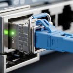
At the enterprise edge, SFP optics sit between the router WAN port and the carrier or aggregation network. Failures are often not “bad optics” but mismatches across link budget, fiber type, connector polish, or DOM handling. IEEE 802.3 defines Ethernet physical layer behavior for optical links, but vendors still diverge on implementation details like receiver sensitivity thresholds and lane/baud tolerances. In the field, the fastest way to reduce outages is to align transceiver optics with the exact fiber plant and the router interface requirements.
Before buying, confirm the router model and WAN port type (10G SFP+, 1G SFP, or other). Then verify whether the platform expects digital optical monitoring (DOM) and whether it supports specific optic vendor IDs. Many routers will light the link with third-party optics, but some enforce compatibility checks that can disable DOM telemetry or log alarms.

What to match: wavelength, reach, and connector polish
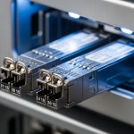
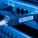
SFP transceivers come in multiple optical “flavors.” The most common enterprise edge choices are 1310 nm for longer reach on single-mode fiber and 850 nm for shorter reach on multimode. You must also match connector and fiber type: LC connectors are typical for SFP/SFP+ optics, and single-mode typically uses OS2 fiber while multimode uses OM3 or OM4. If the connector polish grade is wrong or contamination remains after cleaning, optical power budgets collapse even when the wavelength matches.
Technical specifications you should verify
Use the table below as a baseline for selection. Actual values vary by vendor and exact part number; always confirm against the transceiver datasheet and the router optics support matrix.
| Transceiver example (models) | Data rate | Wavelength | Fiber type | Reach (typ.) | Connector | Optical power class | DOM | Operating temp |
|---|---|---|---|---|---|---|---|---|
| Cisco SFP-10G-SR | 10G | 850 nm | OM3/OM4 multimode | ~300 m (OM3), ~400 m (OM4) | LC | Class 1 laser product | Commonly supported | 0 to 70 C (typ.) |
| Finisar FTLX8571D3BCL | 10G | 850 nm | OM3/OM4 multimode | ~300 m to ~400 m depending on fiber | LC | Class 1 laser product | Often available via DOM | -5 to 70 C (typ.) |
| FS.com SFP-10GSR-85 | 10G | 850 nm | OM3/OM4 multimode | ~300 m to ~400 m | LC | Class 1 laser product | Varies by SKU | -5 to 70 C (typ.) |
| Finisar/compatible 10G-LR SFP+ (typ. 1310 nm) | 10G | 1310 nm | OS2 single-mode | ~10 km | LC | Class 1 laser product | Commonly available | -5 to 70 C (typ.) |
Key fields to validate in the datasheet: transmit wavelength tolerance, receiver sensitivity, minimum and maximum optical power, and whether it is designed for duplex LC with standard fiber. For edge deployments, also check whether the transceiver is rated for the ambient temperature in the cabinet and whether it supports DOM thresholds that your NMS can interpret.
Pro Tip: In many “link up but unstable” cases, engineers confirm distance and wavelength but overlook connector cleanliness and patch-cord attenuation. A single dirty LC connector can add enough loss to push the receiver margin beyond the vendor’s sensitivity spec, especially after planned moves or maintenance.
Deployment scenario: SFP WAN handoff in a leaf-spine edge
Consider a 3-tier data center leaf-spine topology where the edge router terminates WAN circuits into a pair of 10G switches. The edge router uses two 10G SFP+ router fiber interface ports for uplinks to an ISP aggregation demarc, each carrying 8 Gbps peak traffic with bursts. The site uses OM4 multimode for in-building runs of 250 m and OS2 single-mode for the carrier handoff totaling 6.5 km. Engineers install 10G SR optics for the 250 m segment and 10G LR optics for the 6.5 km segment, both with LC connectors and verified DOM visibility.
Operationally, they monitor link health via interface counters and DOM readings (receive power in dBm, laser bias current, and temperature). During acceptance testing, they verify end-to-end optical budget by confirming received power sits within the transceiver’s recommended window and that CRC and FCS errors remain near zero. When a later fiber reroute increases loss by an estimated 2 dB, the team correlates rising receive power margin usage with increased retransmissions and schedules connector cleaning before replacing optics.
Selection criteria checklist for engineers
Use this ordered checklist when choosing transceivers for a router fiber interface at the enterprise edge.
- Distance and fiber plant: confirm actual route length, splice count, patch cords, and whether the medium is OM3/OM4 or OS2.
- Wavelength alignment: pick 850 nm for multimode short reach and 1310 nm for single-mode longer reach.
- Switch and router compatibility: validate the router model’s optics support matrix; check for DOM and vendor ID enforcement.
- Connector and polish grade: match LC duplex; ensure the patch cords use APC/UPC only when the system requires it (most Ethernet optics are UPC).
- DOM support and NMS mapping: confirm your telemetry stack reads the DOM fields you need for alarms.
- Operating temperature and airflow: ensure the transceiver rating covers cabinet ambient and ducted airflow constraints.
- Vendor lock-in risk: compare OEM vs third-party; plan for spares and consistent behavior across sites.
For standards context, confirm that the transceiver aligns with the Ethernet PHY requirements for the port speed. Reference vendor datasheets plus IEEE 802.3 for the underlying physical layer behavior. anchor-text: IEEE 802.3 standard pages
Common mistakes and troubleshooting tips
Below are failure modes you will see during edge deployments, along with root causes and fixes.
- Mistake: Installing an 850 nm SR optic on a single-mode OS2 circuit.
Root cause: wavelength mismatch and modal behavior prevent sufficient receiver power.
Solution: replace with 1310 nm LR (or the correct single-mode optic) and re-verify the fiber type on both ends. - Mistake: Using the correct optic type but with dirty or scratched LC connectors.
Root cause: contamination increases insertion loss beyond the receiver sensitivity margin.
Solution: clean with approved fiber cleaning tools, inspect with a scope, and re-test received power after cleaning. - Mistake: Third-party optics trigger alarms or DOM shows “unknown.”
Root cause: router enforces vendor IDs or DOM interpretation differs from expected thresholds.
Solution: validate against the router’s optics compatibility list; if needed, enable “allow unsupported optics” only after confirming stable link behavior. - Mistake: Link stays up but throughput collapses with rising CRC errors.
Root cause: marginal optical power due to excessive patch cord loss, aged connectors, or additional splices not included in the original budget.
Solution: measure DOM receive power, compare to the datasheet operating window, and remediate the physical path (cord replacement, splice remediation).
Cost and ROI note: OEM vs third-party optics
Pricing varies by speed and reach, but in typical enterprise procurement channels, OEM 10G SR or LR SFP+ optics can range from roughly $60 to $200 per module. Third-party or compatible optics often land in the $30 to $120 range depending on DOM support, brand, and temperature grade. TCO should consider not only unit cost but also failure rates, warranty terms, and the operational cost of troubleshooting compatibility issues.
In edge environments with frequent maintenance windows, ROI improves when optics are consistent across sites and when DOM telemetry reduces mean time to repair. However, if your router platform strictly restricts optics, OEM may still be cheaper overall once you count truck rolls and change-control delays. Always validate with a pilot in a non-critical rack before scaling.
FAQ
What does “router fiber interface” mean in practice?
It refers to the physical WAN or uplink port on your router that uses optical transceivers, commonly SFP or SFP+. In practice, it includes the transceiver type, the fiber connector standard, and the link budget constraints that determine whether the interface stays stable under load.
How do I know whether I need 850 nm or 1310 nm?
Use the fiber type and distance. Multimode short-reach