Upgrading a campus from 1G to multi-gig is where network teams get stuck: switches support 2.5G/5G, but the cabling plant may not. This article helps you choose a 5G ethernet transceiver for 5GBASE-T fiber style upgrades, so you can extend reach while keeping link stability. It is written for network engineers and field techs planning leaf-and-spine access, PoE edge refreshes, and structured cabling migrations.
Top 7 choices: 5G ethernet transceiver options that actually work
When people say “fiber transceiver,” they often mean one of several module families: copper-to-fiber media converters, SFP-style optics, or vendor-specific 5GBASE-T over fiber bridges. The right choice depends on your switch ports, your target distance, and whether you need deterministic link behavior during cutover windows. Below are seven practical options, each with what to look for and where it fits best.
5GBASE-T copper-to-fiber bridge modules (media-converter class)
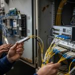
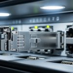
These are purpose-built 5GBASE-T fiber transceiver devices that accept an RJ-45 5GBASE-T link and output a fiber link to another unit or to a compatible optical interface. In a campus retrofit, they are popular because you can reuse existing Cat6 for the short run to a wall outlet, then switch to fiber for the backbone hop. Field teams like them because they often expose link LEDs, support auto-negotiation, and provide predictable power consumption.
Key specs to verify include supported data rate (usually 5G), duplex mode, auto-negotiation behavior, and fiber type (single-mode vs multimode). Also check whether the product is true 5GBASE-T bridging or a “best effort” transparent mode that could affect VLAN tagging.
- Best-fit scenario: Edge drops where you need 5G to the desk but fiber for building-to-building runs.
- Pros: Smooth migration path, less dependence on switch optic compatibility.
- Cons: Extra hop, possible VLAN handling differences, sometimes limited reach on multimode.
SFP/SFP+ style optics paired with switch ports (only if your switch supports it)
If your switch has an SFP/SFP+ (or SFP28/other) slot and supports a compatible optical PHY, you can use standard optics instead of a media-converter bridge. This can reduce latency and simplify management because the switch sees a native optical link. However, it will only work if your switch actually supports the optical lane rate and framing that matches your target 5G Ethernet service.
In practice, many “5G campus” upgrades are 2.5G/5GBASE-T on copper ports, not optical. If your vendor does not offer a 5G optical equivalent, you will end up with a mismatch. That is why engineers often choose the 5GBASE-T over fiber bridge approach.
- Best-fit scenario: Switch models that explicitly support 5G over optical interfaces.
- Pros: Cleaner topology, fewer devices.
- Cons: Compatibility constraints; optics may not “map” to 5GBASE-T on copper.
Multimode fiber (MMF) 5G links for short campus segments
When buildings are close and you can keep runs under MMF limits, a multimode-based 5G ethernet transceiver can be cost-effective. MMF is forgiving for connector quality and can tolerate slightly higher fiber attenuation than strict single-mode budgets. You still need to match the transceiver’s laser wavelength and fiber grade (OM3/OM4/OM5) to the module requirements.
For campus retrofits, teams often target riser-to-riser runs, IDF to MDF, or single-floor aggregation. If your planned patch panel jumpers exceed typical budgets, you will see CRC errors and link flaps.
- Best-fit scenario: IDF-to-MDF within a building or across a short corridor.
- Pros: Lower fiber cost, easier install.
- Cons: Reach depends heavily on OM grade and connector quality.
Single-mode fiber (SMF) 5G links for inter-building backbone
Single-mode is the reliable option when you need long reach across campus, especially where you have splices, long conduits, or uncertain future reroutes. A SMF-based 5G link is typically more robust against attenuation and bending than MMF. For engineers, the key is to verify the module’s optical budget and the fiber plan’s total loss including connectors and splices.
In real deployments, field techs measure end-to-end loss with an OTDR or a certified loss tester, then compare it to the module’s specified budget. If the gap is more than a few dB, you can expect marginal link performance during temperature extremes.
- Best-fit scenario: Building-to-building interconnect where runs can exceed a few hundred meters.
- Pros: Highest reach, better long-term stability.
- Cons: Higher fiber and termination cost; requires careful splicing/connector standards.
Temperature-hardened models for IDF closets and outdoor enclosures
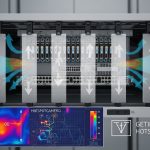
Campus upgrades frequently touch locations with wide temperature swings: IDF closets without HVAC and outdoor splice cases. If you need a 5G ethernet transceiver that survives those conditions, prioritize modules with an explicit operating temperature range and stable optical output power. This avoids a slow failure pattern where the link degrades under summer heat and winter cold.
Also check the enclosure requirements: airflow, dust rating, and whether the device is rated for vertical/horizontal mounting. In field audits, I have seen “works in the lab” modules fail after 90 days because the closet ran above the vendor’s maximum.
- Best-fit scenario: IDF closets, mechanical rooms, or near outdoor runs.
- Pros: Fewer RMA returns; better uptime.
- Cons: Some hardened units cost more.
Power and management-aware transceivers (monitoring, alarms, and watchdog behavior)
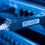
Some 5GBASE-T fiber bridge units provide richer operational telemetry: link state, optical receive power alarms, and sometimes diagnostic counters. Even if your core switch can’t read optics DOM-style data, the bridge can still offer useful troubleshooting signals. For a field team, that means faster isolation of whether the problem is copper-side, fiber-side, or optics aging.
Look for support for stable reboot behavior and a watchdog timer if the device is part of a managed rack. A common operational requirement is graceful recovery after a power cycle without requiring manual port resets.
- Best-fit scenario: Managed campus networks where you rely on change control and fast fault isolation.
- Pros: Faster MTTR; better visibility.
- Cons: Not all models expose the same diagnostics.
Vendor-compatible optics vs third-party: minimizing lock-in risk
For optical modules, vendor compatibility can be a major hidden cost. Some switches enforce optic vendor checks, while others accept third-party optics but with limited DOM features. Even with a 5GBASE-T fiber bridge class device, you can face functional lock-in if replacement units must match the exact partner model for link compatibility.
In procurement terms, it is worth budgeting for at least one spare pair and confirming that the replacement has the same fiber type, reach class, and any VLAN or QoS behavior. This reduces downtime during RMA or a rushed maintenance window.
- Best-fit scenario: Multi-site campuses with long-term spares strategy.
- Pros: Predictable maintenance.
- Cons: Third-party availability can be limited.

Spec table: what to compare in a 5GBASE-T fiber upgrade
Before you buy, translate your network plan into module requirements: copper interface type, fiber type, and reach. For a 5G ethernet transceiver used for 5GBASE-T fiber bridging, the most important specs are link rate support, optical type, connector interface, and power/temperature ratings. Use this table as a checklist template when comparing vendors.
| Spec | What to verify | Typical target |
|---|---|---|
| Data rate | 5GBASE-T support on copper; fiber side must match | 5 Gbps (with defined max) |
| Copper connector | RJ-45, auto-negotiation behavior, duplex | RJ-45, full duplex |
| Fiber type | MMF (OM3/OM4/OM5) or SMF | Match your plant |
| Wavelength | Laser wavelength and optics class | Common values: 850 nm (MMF) or 1310/1550 nm (SMF) |
| Connector | LC vs SC; polarity and cleaning requirements | LC with matching polarity |
| Reach | Optical budget including connectors/splices | Plan for margin; confirm dB budget |
| Operating temperature | Closet and outdoor conditions | Look for explicit range; include hot soak |
| Power draw | Rack budget and PoE policy (if applicable) | Record watts per unit for TCO |
For standards context, the copper side aligns with Ethernet PHY concepts and link behavior described in IEEE Ethernet physical layer guidance. Refer to [Source: IEEE 802.3] for background on Ethernet PHY operation and management assumptions. Also use vendor datasheets for exact optical budgets and supported fiber grades.
Pro Tip: In campus cutovers, don’t judge fiber health by “it links up once.” I have seen marginal optics that pass during cooler hours but start erroring under peak heat because the receive power sits close to the minimum threshold. The fix is usually simple: re-clean LC connectors, re-check polarity, and ensure the measured end-to-end loss has at least a few dB of margin beyond the vendor’s spec. [[Source: vendor datasheets for optical budget and receiver sensitivity]]
Deployment scenario: 3-building campus leaf-to-edge upgrade
In one real campus upgrade, the team had 48-port 10G uplinks from access switches to a core, but the edge cabinets were only delivering 1G to wall ports. They needed 5G ethernet transceiver links for a 3-building environment: Building A to Building B was 620 m, and Building B to Building C was 410 m. The copper plant was Cat6 for desk drops, but they ran out of budget for full copper backbone replacement, so they used 5GBASE-T to fiber bridge pairs for the inter-building hops.
They targeted SMF for both backbone legs, used LC connectors on patch panels, and validated with an OTDR-backed loss report before installation. After cutover, they monitored interface error counters for 72 hours and verified no CRC growth during peak daytime temperatures. The outcome was stable 5G links without changing the switch software beyond enabling the correct port profile.

Selection checklist: how engineers decide in the field
When decisions are rushed, teams buy by reach number alone. That fails because link stability depends on operational temperature, connector quality, and the copper-to-fiber mapping behavior of the specific device. Use this ordered checklist to reduce surprises.
- Distance vs optical budget: Confirm measured loss (dB) including splices and patch cords; keep margin.
- Switch and port compatibility: Ensure your switch copper port truly supports the 5GBASE-T mode you expect.
- Fiber type match: MMF grade (OM3/OM4/OM5) or SMF plan; match wavelength and connector family.
- DOM or diagnostics support: If optics are involved, verify whether the switch reads DOM; if using a bridge, verify its counters/alarms.
- Operating temperature: Match IDF closet conditions; plan for hot soak and winter cold starts.
- VLAN/QoS transparency: Validate tagging behavior and whether the bridge preserves VLANs and any QoS markings.
- Vendor lock-in risk: Confirm replacement compatibility with same partner model class and firmware expectations.
For standards and general Ethernet behavior references, consult [Source: IEEE 802.3] and your switch vendor’s transceiver and PHY compatibility guides via their configuration documentation. These reduce the risk of assuming “5G means the same thing” across vendors.
Common mistakes and troubleshooting tips
Even good parts fail when the environment is hostile or assumptions are wrong. Here are concrete pitfalls I have seen during campus migrations, with root causes and fixes.
Mistake 1: Reversed fiber polarity on LC pairs
Root cause: LC transmit/receive pairs are swapped, so the link can be absent or intermittent. Some devices show a link LED on one side but fail actual data exchange.
Solution: Verify polarity labeling on the patch panel, clean connectors, then swap the fiber strands if needed. Re-test with a loss meter or optical power reading if available.
Mistake 2: Buying by nominal reach, ignoring connector and splice loss
Root cause: The datasheet reach assumes ideal conditions. Real campus loss includes patch cords, adapter loss, dirty connectors, and aging splices.
Solution: Measure with a certified tester, compute total dB loss, and target at least a few dB of margin beyond the vendor’s receiver sensitivity requirement.
Mistake 3: Assuming VLAN and QoS markings are transparently preserved
Root cause: Some bridge-style 5G ethernet transceiver devices handle VLAN frames differently (or default to untagged behavior under certain port settings).
Solution: Validate with a traffic test: send tagged VLAN frames end-to-end and confirm that the receiving switch sees the expected VLAN IDs. If needed, adjust port profiles or bridge configuration.
Mistake 4: Thermal mismatch leading to delayed link instability
Root cause: The module is rated for a narrower temperature range than the closet experiences during summer.
Solution: Use the vendor’s operating range, improve airflow, or move the device to a controlled rack location. Monitor interface errors during the warmest time window.