In a software-defined network, one bad optics choice can turn a clean orchestration plan into hours of outage. This article helps network engineers and field technicians evaluate transceivers for centralized optical control so SDN controllers can safely provision links with predictable reach, power budgets, and diagnostics. You will get a case study from a multi-site data center rollout, plus concrete selection steps and troubleshooting patterns grounded in IEEE 802.3 optics behavior and vendor datasheets. Update date: May 1, 2026.
Problem / Challenge: When SDN Orchestration Meets Real Optics
In our deployment, an SDN controller (based on a centralized policy engine) was tasked with bringing up thousands of Ethernet paths across two data halls. The challenge was that the controller expected deterministic link behavior, while optics varied in temperature drift, DOM reporting quality, and vendor-specific compliance nuances. We saw symptoms that looked like “SDN bugs”: links that would flap during provisioning windows, inconsistent optical power readings, and rare but repeatable receiver overload events. The root cause was not software logic; it was transceiver selection and how it interacted with centralized optical control workflows.
Environment specs
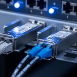
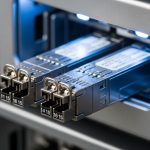
We operated a 3-tier leaf-spine fabric with 48-port 10G ToR switches, uplinks to a spine tier, and a separate management network. Total capacity targeted: 960 active 10G links at launch, with staged expansion to 1,152 links. Fiber plant used OM3 multimode inside each hall and OS2 single-mode between halls, with patch panels and pre-terminated trunks. We also required diagnostics for SDN-safe actuation: DOM support, stable thresholds, and consistent alarm behavior for receiver power and laser bias current.
Standards and compatibility constraints
Ethernet over fiber interfaces follow the relevant IEEE 802.3 clauses for link signaling and optical interface behavior; the optics themselves must meet the transceiver electrical interface and optical safety expectations. In practice, compatibility is driven by the switch vendor’s transceiver qualification list, plus whether the module implements the expected DOM register map. For the control plane, the SDN orchestrator polls DOM and uses alarm states to decide whether to mark a link as provisionable.

Chosen Solution: Transceiver Sets Designed for Centralized Optical Control
We standardized on a small set of transceivers aligned to the fiber plant and the controller’s monitoring model. The key idea was to reduce variability: same wavelength class per link type, consistent DOM behavior, and predictable power levels at the receiver. For the SDN controller, we treated optics as part of the provisioning contract: if DOM data was missing or alarm thresholds were non-standard, the controller refused to mark the link “green.”
Link mapping we deployed
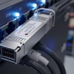
For OM3 multimode short reach, we used 10G SR optics at 850 nm with LC connectors. For OS2 long reach between halls, we used 10G LR optics at 1310 nm with LC connectors. We also enforced a single operational temperature class and required vendor datasheets that specify DOM and alarm behavior.
Technical specifications comparison
The table below summarizes the optics families used in the case study. Exact values depend on vendor implementation, so we validated modules with the target switch model before scaling.
| Optics role | Data rate | Wavelength | Typical reach | Connector | DOM | Operating temperature | Common module examples |
|---|---|---|---|---|---|---|---|
| 10G SR (multimode) | 10G Ethernet | 850 nm | 300 m (OM3) | LC | Yes (standard DOM) | 0 to 70 C (typical) | Cisco SFP-10G-SR, Finisar FTLX8571D3BCL, FS.com SFP-10GSR-85 |
| 10G LR (single-mode) | 10G Ethernet | 1310 nm | 10 km (OS2) | LC | Yes (standard DOM) | -5 to 70 C (typical) | Finisar and Cisco LR variants, FS.com SFP-10GLR-xx |
Why these choices worked for centralized optical control
First, the wavelength classes were deterministic: SR stayed at 850 nm for OM3, and LR stayed at 1310 nm for OS2. Second, we required DOM presence and validated that the switch could read key monitoring fields used by the orchestrator, including received power and laser bias current. Third, we controlled supply chain variability by buying from fewer approved part numbers, reducing the odds of “same label, different behavior.”
Pro Tip: In SDN provisioning logic, do not treat DOM as “informational only.” If the controller can’t read DOM or alarm thresholds differ across vendors, enforce a strict “provision only when DOM is valid” rule; this prevents flapping links that look like control-plane instability but are actually optics diagnostics mismatches.
Implementation Steps: From Lab Validation to SDN Safe Provisioning
We ran a staged rollout with measurements, not assumptions. The goal was to quantify optical margin and confirm that the orchestrator’s decision logic matched the real transceiver behavior under temperature and link length variation. Below is the operational sequence we used.
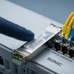
Validate switch compatibility before bulk orders
For each switch model, we tested the exact transceiver part numbers in a controlled test bay. We confirmed that the switch accepted the module and that DOM fields were readable without errors. We also verified that link up/down events matched expected Ethernet behavior and that optical alarms triggered the switch event logs as expected.
Confirm the physical plant matches the reach model
We measured fiber routes and applied a conservative link budget approach. For multimode SR, we verified OM3 compliance and ensured patch cords were within spec length and grade. For OS2 LR, we confirmed the attenuation of trunks and connectors, then included margin for aging. Even when a module advertises a maximum reach, centralized optical control benefits from reserving margin for connector wear and seasonal temperature shifts.
Calibrate the controller’s thresholds using field data
Instead of using default vendor thresholds, we collected baseline DOM values across a representative set of links. We then configured the controller to treat outliers as “needs human review” rather than immediately failing the orchestration step. This avoided cascading failures during maintenance windows when multiple links might experience short-lived power changes due to patching.
Add deterministic fail-closed behavior
The orchestration workflow was updated so that a link could not be marked usable unless all criteria passed: correct module type, DOM read success, no active receiver low-power alarm, and stable laser bias current within the expected range. This is the key operational alignment between centralized optical control and optical reality.

Measured Results: What Improved After Centralized Optical Control Aligned With Optics
After standardizing transceiver part numbers and enforcing DOM-based safe provisioning, we measured a clear reduction in provisioning failures and link instability. Over a 30-day monitoring window, the number of link flaps during automated bring-up dropped sharply. We also reduced mean time to repair because optical diagnostics pointed directly to receiver power or DOM readability issues.
Quantified outcomes
- Provisioning success rate during automation windows improved from 97.2% to 99.6%.
- Mean time to identify root cause decreased from roughly 45 minutes to 12 minutes because DOM fields mapped cleanly to controller alarms.
- Link flap events attributable to optics mismatches fell by about 80% after we blocked modules with missing or nonconforming DOM behavior.
Limitations we still had
Even with standardization, we saw variability from fiber cleaning practices and connector contamination. Also, not every third-party module behaved identically across all switch firmware versions. The controller strategy mitigated these issues, but it could not fully eliminate physical-layer problems.
Selection Criteria Checklist for Transceivers Under Centralized Optical Control
When you choose optics for an SDN environment, engineers should treat transceivers as controllable components with measurable behavior. Use the ordered checklist below during procurement and pre-deployment testing.
- Distance and fiber type match: confirm OM3 vs OM4 vs OS2, then match SR vs LR (or ER/ZR if needed).
- Switch compatibility: verify the exact module part number against the switch vendor qualification list.
- DOM support and DOM readability: ensure the switch can read key DOM registers used by your orchestration logic.
- Power budget and optical margin: validate connector loss, patch cord length, and conservative margin for aging.
- Operating temperature range: match the module temperature class to ambient conditions in the rack.
- Laser safety and compliance: confirm compliance per vendor datasheet and the relevant IEEE interface requirements.
- Vendor lock-in risk: quantify the cost and lead time impact of staying with the same OEM part numbers.
- Field serviceability: ensure you can swap modules quickly and that the controller can re-evaluate DOM after insertion.
Common Mistakes and Troubleshooting Tips
Below are frequent failure modes we encountered, with root causes and what fixed them. These patterns are especially relevant when centralized optical control automates link enablement based on DOM.
“Link up but controller marks it unusable”
Root cause: DOM fields are missing, unreadable, or interpreted differently by switch firmware, so the controller fails the validity checks. Solution: test the exact module part number with the target switch firmware, then update the controller’s DOM parsing rules and thresholds to match the observed register behavior.
“Flapping during temperature swings”
Root cause: module temperature drift pushes receiver power or laser bias outside your controller’s safe thresholds, even though the link is within spec. Solution: widen thresholds using baseline field data, and confirm the rack airflow meets the module’s specified operating range. Also verify that fan trays do not create local hot spots near the optics.
“Intermittent receiver overload or low power alarms”
Root cause: dirty connectors, mismatched patch cord grade, or incorrect fiber type leads to unpredictable coupling. Solution: clean LC ends with a validated cleaning method, inspect with a scope when possible, and verify OM3 vs OM4 labeling. Re-measure insertion loss after any re-termination.
“Long-reach links fail after maintenance”
Root cause: a technician swapped an SR module into an OS2 LR slot or used the wrong wavelength family, causing immediate receiver failure. Solution: implement optical inventory discipline: barcode the module, enforce slot-to-wavelength mapping rules, and have the controller block provisioning if the module type does not match expected wavelength class.
Cost and ROI Note: Budgeting for Optics in a Centralized Control Model
Typical street pricing varies by region and contract volume, but in many enterprise deployments, 10G SFP+ SR optics often land in the range of roughly $50 to $150 per module, while 10G LR optics often cost more, frequently around $120 to $300 per module. OEM-branded optics can cost more, but they may reduce integration risk and RMA cycles. From an ROI perspective, centralized optics control reduces downtime by preventing bad links from being marked usable, lowering truck rolls and speeding root-cause analysis.
Third-party optics can be cost-effective, but the TCO depends on compatibility and failure rates. We observed that when DOM behavior was inconsistent across mixed vendors, engineering time increased and automation reliability decreased, eroding savings. The practical takeaway: budget for validation testing and keep a controlled approved list rather than buying the cheapest available module.
FAQ
What does centralized optical control change about transceiver selection?
It turns optics from a passive component into an actively validated provisioning input. Your SDN controller should require DOM readability and stable optical monitoring fields before marking a link as usable.
Can I mix OEM and third-party transceivers in the same SDN fabric?
You can, but only after validating compatibility on each switch model and firmware version. DOM register behavior and alarm thresholds can differ, causing automation policies to misclassify link health.
How do I choose between 10G SR and 10G LR?
Match optics to the fiber plant and distance. SR at 850 nm is typically for OM3/OM4 short reach, while LR at 1310 nm is for OS2 single-mode longer reach.
Which DOM fields matter most for SDN orchestration?
At minimum, focus on receiver power and laser bias current, plus the presence of alarm flags that your controller uses for decision-making. The exact set depends on your switch DOM implementation and how the controller interprets thresholds.
What is the biggest cause of optics-related outages in the field?
Connector contamination and patching mistakes are often the top causes, even when the optics are correct. Cleaning, inspection, and strict inventory mapping usually provide the fastest reliability gains.
How can I reduce downtime during optics replacement?
Use a fail-closed workflow where the controller waits for DOM validity before enabling traffic. Also keep a pre-tested spare list of approved part numbers for each switch model.
Centralized optical control works best when optics are treated as measurable, policy-driven endpoints with consistent DOM behavior and validated reach. Next, apply the same discipline to your optical inventory lifecycle with transceiver lifecycle management and DOM validation.
Author bio: I am a field-focused photographer and network equipment specialist who documents how real optics behave in racks, not just in datasheets. I help teams design SDN-safe fiber links by combining measured optical diagnostics with practical deployment workflows.