In a 3-tier data center, a few marginal optics can quietly drain utilization: links flap, BER rises, and capacity planning becomes guesswork. This article helps network and field engineers implement centralized optical control to standardize transceiver behavior, monitor optical health, and reduce avoidable downtime across racks and sites. You will get practical selection criteria, a real deployment example with numbers, and troubleshooting patterns you can apply on your next maintenance window.

What “centralized optical control” means in day-to-day operations
Centralized optical control is the operational model where optical-layer telemetry and configuration are managed from a common control plane (typically the network management system plus vendor or standards-based telemetry hooks). In practice, teams correlate transceiver diagnostics, link status, and error counters with topology intent so they can forecast failures and enforce consistent optics policy. The goal is not only monitoring, but also faster, safer intervention when optical parameters drift.
On the standards side, most modern optics expose diagnostics through the vendor-defined management interface and common digital diagnostic patterns (often following the Digital Optical Monitoring conventions used by QSFP/SFP families). For Ethernet link behavior, the underlying performance expectations map to IEEE 802.3 physical layer operation, including how link training and error correction interact with BER and link flaps. For reference, see [Source: IEEE 802.3] [[EXT:https://standards.ieee.org/standard/]].
Where control actually lives
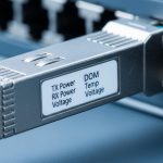
- Telemetry collection: DOM-like readings such as received power (Rx), transmit power (Tx), temperature, supply voltage, and vendor alarms.
- Event correlation: tying optical alarms to interface counters (CRC, FCS, PCS/PMA errors), switch logs, and physical patching records.
- Policy enforcement: flagging unsupported modules, preventing risky mixed-revision optics, and guiding rollbacks during upgrades.
Pro Tip: In the field, the fastest reliability wins usually come from alerting on rate-of-change in Rx power and temperature, not just absolute thresholds. A gradual 1 to 2 dB Rx drop over weeks often precedes hard failures, and centralized optical control makes it easy to compare baselines across racks.
Key specs that determine whether centralized optical control will help
Centralization only pays off if your optics and switches provide consistent diagnostics, predictable thresholds, and stable compatibility. When modules lack detailed monitoring (or the switch firmware ignores diagnostics), you end up with partial visibility and more manual site work. Engineers should align optics selection with the link budget and the telemetry quality your control plane can ingest.
Below is a practical comparison for common Ethernet optics used with centralized monitoring. Values vary by vendor and part number, so treat them as planning baselines and verify against datasheets for your exact modules and switch transceivers.
| Parameter | 10G SR (SFP+) | 10G LR (SFP+) | 25G SR (SFP28) | 100G SR4 (QSFP28) |
|---|---|---|---|---|
| Typical wavelength | 850 nm | 1310 nm | 850 nm | 850 nm (parallel lanes) |
| Reach (typical) | Up to 300 m on OM3/OM4 | Up to 10 km on single-mode | Up to 100 m on OM3/OM4 | Up to 100 m on OM4 (varies) |
| Connector style | LC | LC | LC | MPO-12 (or MPO-16) |
| Data rate | 10.3125 Gb/s | 10.3125 Gb/s | 25.78125 Gb/s | 103.125 Gb/s (4 lanes) |
| DOM / diagnostics | Rx/Tx power, temp, voltage (module-dependent) | Rx/Tx power, temp, voltage (module-dependent) | Rx/Tx power, temp, voltage (module-dependent) | Rx/Tx power per lane, temp, voltage (module-dependent) |
| Operating temperature | Commercial or Industrial variants (verify) | Commercial or Industrial variants (verify) | Commercial or Industrial variants (verify) | Commercial or Industrial variants (verify) |
| Power / risk note | Higher reuse risk if mixed vendors without policy | More sensitive to fiber contamination and patch quality | More sensitive to dirty MPO/LC ends on short links | Connector cleanliness and polarity dominate failures |
If you are standardizing optics for centralized optical control, start by selecting transceiver families your switches reliably support. Common examples include Cisco SFP-10G-SR, Finisar FTLX8571D3BCL, and FS.com SFP-10GSR-85 (verify compatibility lists and firmware support for your exact switch models). For optical performance expectations and interface behavior, consult vendor datasheets and switch transceiver compatibility matrices; for Ethernet physical layer expectations, consult IEEE 802.3 family documents. IEEE [Source: IEEE 802.3] and vendor datasheets [Source: Cisco Transceiver Documentation], [Source: Finisar/Viavi Datasheets].

Deployment scenario: centralized control in a leaf-spine rollout
In a leaf-spine data center with 48-port 10G ToR switches and 16-port 100G spine uplinks, the team faced recurring “mystery” utilization drops after patch changes. During a 6-week migration, they introduced centralized optical control to normalize optics telemetry collection across 32 racks. They pulled DOM-like metrics every 60 seconds, correlated them with interface error counters, and generated alerts when Rx power drift exceeded a configured slope.
Operationally, they reduced mean time to detect (MTTD) from roughly 2 hours (manual review of interface errors) to 8 minutes (automated optical trend alerts). During the same window, they cut repeat maintenance calls by identifying two dirty MPO-terminated links before hard failure, preventing a planned capacity test from being invalid. The biggest win came from policy enforcement: the controller blocked non-approved optics revisions on specific uplink ports and flagged mixed-vendor modules as “high risk” until validated.
Limitations remained: not every transceiver family exposed the same diagnostic granularity, and some switch firmware versions required explicit enabling of enhanced transceiver reporting. That is why the control-plane design must be tested in staging with representative modules and the same switch software you will use in production.
Selection criteria and decision checklist for engineers
Use this ordered checklist during procurement and lab validation. It is designed to prevent the common failure mode where you centralize telemetry but cannot act on it confidently.
- Distance and fiber type match: confirm OM3/OM4 vs single-mode, patch loss budget, and connector quality. For SR links, budget for worst-case patch loss and aging.
- Switch compatibility: verify the switch model’s transceiver compatibility list and firmware behavior for diagnostics. Do not assume “any LC SR works.”
- Telemetry completeness (DOM quality): confirm Rx/Tx power availability, lane-level metrics for multi-lane optics, and supported alarm flags. Aim for consistent fields across vendors if you plan to mix.
- Control-plane integration: ensure your centralized optical control system can ingest telemetry at your desired cadence (example: 60 s interval) without overwhelming collectors.
- Operating temperature range: select industrial-grade optics when intake air is unstable; verify the module’s guaranteed temperature envelope in the datasheet.
- Vendor lock-in risk: evaluate whether third-party optics are accepted and whether their diagnostics map cleanly into your control model.
- Power and thermal budget: ensure the switch’s optics power envelope supports the module class; confirm airflow assumptions in dense pods.
Common pitfalls and troubleshooting patterns
Even with centralized optical control, optics failures can still happen. The difference is whether you detect and isolate them quickly with accurate root cause. Here are frequent mistakes that field teams see, with actionable fixes.
Pitfall 1: “We have alerts, but they are noisy”
Root cause: thresholds are set to vendor defaults, but your environment differs (hotter aisles, different patch loss, different baseline received power). The controller triggers on normal variance.
Solution: establish baselines per link group after burn-in. Use slope-based alerts (trend) in addition to absolute thresholds, and set separate profiles for short-reach vs long-reach optics.
Pitfall 2: “Telemetry exists, but control actions do nothing”
Root cause: the switch does not expose full diagnostics to the management plane for that port speed, or firmware blocks enhanced transceiver reporting. Centralized optical control becomes read-only.
Solution: validate in a staging rack: confirm the specific switch OS version supports transceiver diagnostics on your port types. If needed, align to supported firmware and re-test with the exact module part numbers (for example Cisco SFP-10G-SR vs a third-party SR with different diagnostic behavior).
Pitfall 3: “Link flaps after patching, but BER counters look inconsistent”
Root cause: polarity issues, wrong patch type, or dirty connectors. With MPO-based optics, a single mis-termination can cause lane imbalance that intermittently trips error thresholds.
Solution: enforce cleaning and inspection workflow: inspect with a fiber microscope, clean using lint-free procedures, and verify polarity with an MPO polarity kit. In centralized optical control, correlate lane-level Rx power anomalies to immediately flag likely polarity or connector contamination.
Pitfall 4: “Mixed optics vendors cause false risk flags”
Root cause: diagnostic scaling or alarm semantics differ across vendors, so the controller interprets values inconsistently.
Solution: normalize using per-vendor calibration rules or restrict to a vetted optics set for each link class. Track failure rates by vendor and keep an exception process rather than a blanket policy.
Cost and ROI considerations for centralized optical control
Pricing varies widely by transceiver type and vendor. As a realistic planning range, third-party optics often price 10% to 35% lower than OEM modules, but the total cost depends on compatibility risk, warranty handling, and the operational cost of troubleshooting. Centralized optical control typically adds software licensing (or integration effort) plus telemetry collection resources.
For ROI, teams usually count: reduced downtime hours, fewer truck rolls, and fewer invalid test windows. If you prevent even 1 to 3 unplanned incidents per quarter on a multi-rack environment, the payback can be fast—especially where optical failures are difficult to diagnose without centralized Rx power trend history. Still, do not ignore TCO: misconfigured alerts can create engineering time waste, and a partial telemetry setup can increase operational churn.
FAQ
How does centralized optical control improve utilization, not just monitoring?
It improves utilization by reducing link downtime and avoiding “silent degradation” where BER rises before a full outage. With early optical drift alerts and correlated error counters, engineers can fix optics before throughput collapses during traffic spikes.
Will it work with third-party transceivers?
Often yes, but compatibility and diagnostics consistency are the deciding factors. Validate that your switch firmware exposes the required diagnostics fields and that your control model can interpret vendor-specific alarm semantics reliably.
What telemetry interval is practical for large networks?
A common operational choice is 60 seconds, balancing responsiveness with collector load. For very large fabrics, you may use adaptive sampling: faster checks during maintenance windows and slower polling during steady state.
Which standards or references should I cite in design reviews?
Use IEEE 802.3 for Ethernet physical layer behavior and vendor datasheets for optics diagnostic availability and optical budgets. In your documentation, also reference ANSI/TIA cabling practices when discussing fiber link quality and connector handling; cite the specific transceiver family datasheets you deploy. ANSI/TIA
What is the most common root cause of sudden optical failures?
Connector contamination and patching mistakes are top causes, especially after moves, adds, and changes. Centralized optical control helps by surfacing lane-level or Rx-power anomalies that point to specific interfaces quickly.
How do I prevent vendor lock-in while keeping diagnostics reliable?
Define “optics classes” with strict acceptance tests: reach, wavelength, DOM field mapping, and alarm behavior. Keep a small validated cross-vendor list per class, and require a diagnostic normalization check before expanding procurement.
Centralized optical control turns optics from a reactive maintenance problem into a measurable reliability system, improving detection speed and reducing avoidable outages. Next, align your transceiver selection and telemetry mapping using fiber-optic-transceiver-compatibility-checklist.
Author bio: I design and deploy optical monitoring workflows for high-density Ethernet fabrics, focusing on actionable telemetry and safe automation. I have supported field rollouts across leaf-spine environments, tuning alert thresholds and compatibility testing to reduce downtime.