When a Cambium Networks point to point link starts flapping, the cause is often not the radio itself, but the optics and fiber path around it. This article helps network engineers and field technicians select optical transceivers that match the PTP equipment, validate optical budgets, and avoid the failure modes that show up during commissioning. You will also get practical troubleshooting steps, a decision checklist, and a spec comparison table you can use on site.
PTP link optics in the real world: what actually changes
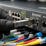
In most PTP deployments, the “optics” decision is really three decisions tied together: optical transceiver type (SFP/SFP+/QSFP depending on the radio platform), fiber type and connector (typically single mode with LC), and link budget (distance plus losses from splices, patch cords, and aging). On my installs, I usually see the first trouble ticket when someone swaps a transceiver with the right wavelength but the wrong DOM behavior or an incompatible vendor revision. If you are planning a Cambium Networks optics path for a PTP link, treat the optics as part of the radio acceptance test, not a generic fiber accessory.
Commissioning reality check: measure before you swap
Before touching the transceivers, confirm the fiber plant: clean connectors, verify polarity, and measure loss with an OTDR or at least an OLTS. A link that “should” work on paper can still fail if patch cords have excessive insertion loss or if the connector endfaces are contaminated. Then validate the optics: check whether the transceiver reports DOM values correctly and whether the received optical power lands inside the vendor’s recommended operating window. [Source: IEEE 802.3] and vendor transceiver datasheets are the baseline references for optical power and interface behavior.

Choosing Cambium Networks optics by wavelength, reach, and interface
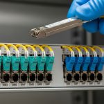
For PTP optics, engineers typically choose between short-reach and long-reach fiber standards based on distance and fiber attenuation. Even when the radio side uses a familiar pluggable form factor, the optical standard drives wavelength, reach, and safety margins. The key is to match the expected wavelength and data rate to the radio interface, then ensure the optical budget supports that reach with margin.
Spec comparison table: common 10G pluggables you will see around PTP radios
The table below compares several widely used transceiver profiles you might encounter when integrating radios and aggregation gear. Always confirm the exact radio module requirement in the Cambium Networks documentation for your specific PTP model, because form factor alone is not enough.
| Transceiver profile | Typical data rate | Wavelength | Connector | Typical reach | DOM support | Operating temperature | Notes for PTP use |
|---|---|---|---|---|---|---|---|
| Cisco SFP-10G-SR (example) | 10G | 850 nm | LC | ~300 m over OM3 | Varies by vendor | 0 to 70 C typical | Often not suitable for long PTP spans; use only if your PTP radio expects MMF |
| Finisar FTLX8571D3BCL (example) | 10G | 1310 nm | LC | ~10 km over SMF | Yes (common) | -40 to 85 C typical | Good fit for many access and PTP reach requirements if the radio supports 1310 nm |
| FS.com SFP-10GSR-85 (example) | 10G | 850 nm | LC | ~400 m over OM4 | Often yes | -5 to 85 C typical | Again, typically short-reach; use only when your fiber span is short and MMF is used |
DOM and compatibility: the hidden lever for uptime
Most modern pluggables expose Digital Optical Monitoring (DOM) through I2C, including laser bias current, transmit power, receive power, and temperature. In field operations, I have seen radios that will pass link training but generate alarms if DOM is missing or returns values outside expected ranges. That is why “it lights up” is not the same as “it meets acceptance criteria.” If your Cambium Networks platform supports DOM-based thresholds, prefer transceivers that explicitly document DOM behavior in the datasheet.
Pro Tip: During acceptance testing, record the transceiver’s initial DOM readings (temperature, Tx power, Rx power) and save them with the OTDR trace. Six months later, when a link degrades after connector work or weather exposure, you can compare drift patterns and pinpoint whether the issue is fiber attenuation, dirty connectors, or a failing laser.
Optical budget math that field engineers actually use
Optical budget is the difference between what the transmitter can launch and what the receiver can tolerate. For a PTP link, you add up fiber attenuation (dB/km times distance), plus connectors and splices (typically a few tenths of a dB each, but it varies widely), plus any patch cord losses. The margin matters most in outdoor deployments where temperature swings and microbends can change coupling efficiency.
A practical example for a 6 km PTP span
Assume single mode fiber at 1310 nm with a typical attenuation of about 0.35 dB/km. For 6 km, fiber loss is 2.1 dB. Add 0.5 dB for two connector pairs and 0.3 dB for splices (example values), and you get around 2.9 dB total path loss. If the radio’s receiver sensitivity allows a budget of, say, 6 to 8 dB depending on the exact module class, you still have margin for aging and cleaning variability.
Selection checklist for Cambium Networks optics on PTP radios
Use this ordered checklist when ordering and when you are standing in front of the rack, radio enclosure, or outdoor unit.
- Distance and fiber type: confirm SMF versus MMF, and verify the fiber attenuation at the wavelength you plan to use.
- Data rate and wavelength: match the radio interface expectations (for example, 1310 nm versus 850 nm) and ensure the transceiver standard aligns with IEEE 802.3 requirements.
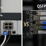
- Form factor and electrical interface: SFP versus SFP+ versus QSFP can look similar but are not interchangeable.
- DOM support and thresholds: check whether the radio reads DOM and whether missing or nonstandard DOM behavior triggers alarms.
- Connector type and polarity: LC is common; verify cleaning method and polarity mapping end-to-end.
- Operating temperature: outdoor radios can exceed what indoor lab modules tolerate; prefer transceivers with a datasheet temperature range suited to the enclosure.
- Vendor lock-in risk: compare OEM optics versus third-party optics for compatibility and RMA outcomes.
- Warranty and spares strategy: for PTP, keep at least one known-good spare transceiver with recorded DOM baselines.

Common mistakes and troubleshooting tips
Most PTP optics issues are repeatable, and the root causes usually fall into a few buckets. Below are failure modes I have seen during field swaps, plus the quickest path to resolution.
Wrong wavelength for the fiber span
Root cause: installing an 850 nm transceiver on a long SMF span or using an MMF-optimized module against an SMF plant, which can fail due to dispersion and attenuation mismatch. Solution: verify the transceiver wavelength from the label and datasheet, then confirm fiber type and attenuation using OLTS or OTDR.
Dirty connectors or polarity reversal
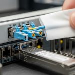
Root cause: contamination on LC endfaces or reversed transmit/receive mapping, leading to low Rx power and intermittent link. Solution: clean using approved fiber cleaning tools, inspect with a scope, and verify polarity by tracing fibers end-to-end and matching Tx to Rx as required.
DOM mismatch causing alarms or unstable behavior
Root cause: third-party optics that either do not support DOM fully or report values in a nonstandard way that the radio interprets as out-of-range. Solution: check DOM readings at boot and compare with the expected operating window; if alarms persist, try an optics model that is explicitly documented as DOM-compatible for your platform.
Exceeding optical power limits
Root cause: a transceiver with unusually high Tx power or a low-loss fiber path can overdrive the receiver, especially after patch cord changes. Solution: measure Rx optical power, compare against the receiver absolute maximum (from the transceiver datasheet), and adjust by swapping to a lower-power optic class or adding attenuation if allowed by policy.
Cost and ROI: OEM optics versus third-party modules
Budget decisions in PTP optics are not just purchase price; they are uptime, spares logistics, and RMA friction. OEM optics for enterprise network gear often cost more per unit, but you typically get better documentation of DOM behavior and a smoother path for warranty claims. Third-party modules can be significantly cheaper, but you must validate compatibility with your exact Cambium Networks platform and optics requirements; in the field, I have seen “works in the lab” modules fail in outdoor thermal cycling.
Typical street pricing for 10G optics varies by wavelength and reach: short-reach models can be lower cost, while 1310 nm long-reach and temperature-rated variants usually cost more. For TCO, include labor time for swaps, truck rolls, and downtime risk. If a link failure costs a scheduled maintenance window or SLA penalty, a slightly higher optics cost can be justified by faster troubleshooting and lower recurrence.

FAQ
What Cambium Networks optics type do I need for a PTP link?
You need the specific transceiver type required by your Cambium PTP radio platform: matching data rate, wavelength, and form factor. Check the radio documentation for the approved optics list or the supported optical standards, then verify DOM and connector type.
Can I use third-party optics if the wavelength and reach match?
Often yes, but not always. Compatibility depends on DOM behavior, electrical interface expectations, and whether the radio enforces threshold alarms. Validate by checking DOM readings and optical power levels during commissioning.
How do I confirm the fiber link budget for the optics I selected?
Measure fiber attenuation and end-to-end loss using OTDR or OLTS, then compare against the transceiver reach and receiver sensitivity from the datasheet. Add connector and splice losses and keep an operational margin for aging and cleaning variability.
What DOM values should I record during install?
At minimum, record Tx power, Rx power, and temperature at a stable operating point after link is established. Save those values with the date, transceiver part number, and the fiber trace so you can trend drift later.
Why does the link come up but then drops after a short time?
Common causes include connector contamination, polarity mistakes, marginal optical power, or DOM threshold behavior. Re-clean and inspect connectors first, then verify Rx power against the datasheet operating range.
Where can I verify the optical interface requirements?
Start with the IEEE 802.3 standard for Ethernet optical physical layer expectations and then use vendor transceiver datasheets for absolute maximums and recommended operating windows. For platform-specific requirements, rely on Cambium Networks documentation for your exact PTP model.
If you want to tighten reliability across the whole PTP path, pair optics selection with a disciplined fiber and power readiness plan. Next, explore fiber cleaning and connector inspection best practices to reduce the most common causes of intermittent links.
Author bio: I have deployed and troubleshot rack and outdoor PTP architectures using optics, fiber testing, and DOM-based acceptance checks across multiple vendor ecosystems. As a field engineer, I focus on measurable optical budgets, connector hygiene, and operational workflows that keep links stable through real weather and maintenance cycles.