If you are deploying Quantum Key Distribution over existing fiber, the hardest part is often not the cryptography itself, but the transceiver and optical link engineering needed to keep the system stable. This article helps network engineers and field teams design a secure fiber link that supports QKD, from selecting the right optical interface to validating power, temperature, and optical budgets. You will get an implementation-style checklist, a comparison of common transceiver parameters, and practical troubleshooting for real failure modes.
Prerequisites before you touch the QKD transceiver
Before ordering optics, confirm your QKD platform requirements and the physical fiber path. QKD systems typically use very specific wavelengths and link budgets, and they may require low-loss channels, strict connector cleanliness, and controlled polarization or dispersion depending on the design. Start with an inventory: fiber type (SMF-28 class vs other), core count, patch panel layout, and measured attenuation using an OTDR or calibrated power meter.
Also gather operational constraints from the QKD vendor: recommended transceiver family, DOM or EEPROM compatibility, allowed optical power range at the receiver, and supported temperature range. For standards alignment, review IEEE Ethernet optics guidance for SFP/SFP+/QSFP electrical behavior and link monitoring expectations, and pair it with QKD vendor documentation for optical safety margins. For background on physical-layer requirements, see [Source: IEEE 802.3] IEEE 802.3.
Step-by-step: implement a QKD secure fiber link using the right transceiver
Use this as a field implementation playbook. The goal is to keep the QKD channel within the vendor’s optical budget while ensuring your network optics do not accidentally violate safety limits or introduce excessive reflections.
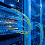
Verify fiber attenuation, reflections, and patching plan
Measure end-to-end loss with OTDR and a calibrated optical power meter for the wavelength band your QKD uses. If your QKD uses a dedicated wavelength and you are multiplexing with classical traffic, confirm the mux/demux insertion loss and isolation. Target connector cleanliness and low reflectance; in practice, teams often clean and inspect connectors under a microscope at every patch change.
Expected outcome: You can state the worst-case attenuation and reflection risk for the QKD channel and identify which patch cords or adapters must be replaced.
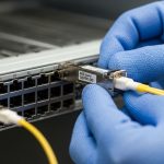
Choose transceiver type by wavelength and QKD vendor interface
QKD systems are not “generic optics in a cage.” Many QKD modules rely on vendor-specific optical wavelengths, receiver sensitivities, and sometimes specialized modulation formats. Your transceiver choice must match the QKD unit’s transmitter wavelength and the receiver’s expected optical power range, not just the reach printed on a datasheet.
When QKD is integrated with network gear, teams often use standard pluggable optics for the classical side, while QKD uses its own channel optics. If your QKD platform uses an SFP/SFP+ style optical interface, confirm that the module supports the required wavelength, fiber type, and DOM behavior demanded by the host.
Example module families you may see in classical optics (not automatically compatible with QKD) include Cisco SFP-10G-SR, Finisar FTLX8571D3BCL, or FS.com SFP-10GSR-85; always validate against the QKD vendor interface requirements before assuming interoperability.
Validate link budget with measured power, not assumptions
Compute your optical budget using measured values: transmitter output power, mux/demux insertion loss, splice loss, connector loss, and patch cord loss. Then compare to the QKD receiver sensitivity and required optical margin. If the QKD vendor specifies a minimum received power, you must ensure you do not fall below it in the worst temperature and aging scenario.
Expected outcome: Your “worst-case received power” is within the QKD vendor’s allowed window with margin for cleaning cycles and patch changes.
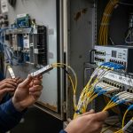
Match connector geometry and cleanliness to reduce QKD channel degradation
Reflections and contamination can degrade QKD performance by increasing noise and destabilizing detection. Use end-face inspection for every connector that touches the QKD optical path. Replace any questionable patch cords and avoid mixing adapters that introduce non-standard ferrule alignment.
Expected outcome: Optical inspection reports show clean end faces, and re-measurement confirms stable received power and consistent QKD session performance.
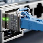
Confirm DOM, alarms, and monitoring behavior for secure fiber link operations
For pluggable optics, ensure the DOM fields (temperature, laser bias, received power, and sometimes supply voltage) are read correctly by the host. Host firmware may enforce thresholds; if the transceiver reports unexpected values or is not recognized, the system may disable the link. Plan an operations runbook: what alarms trigger maintenance, how quickly you respond, and how you re-baseline after cleaning or module replacement.
Expected outcome: You can monitor key optical parameters in real time and correlate them to QKD session stability.
Pro Tip: In field deployments, QKD failures often correlate less with “total loss” and more with connector cleanliness and reflection events after routine maintenance. Teams that implement a connector inspection gate (before and after any patch change) typically reduce unexplained QKD session drops dramatically, even when OTDR loss looks unchanged.
Key transceiver specifications that matter for a QKD secure fiber link
Even if QKD uses specialized channel optics, the transceiver’s optical parameters still govern whether your secure fiber link will remain within the QKD system’s detection window. Below is a practical comparison of common pluggable optics parameters engineers check during procurement and acceptance testing.
| Spec category | What to verify | Typical values (examples) | Why it matters for QKD |
|---|---|---|---|
| Wavelength | Exact center wavelength band | 850 nm (SR), 1310/1550 nm (varies by product) | Mismatched band can cause complete link failure or excessive noise |
| Reach | Rated distance for the module | ~300 m for 850 nm SR class; depends on budget | QKD requires a strict received-power window, not just “it lights up” |
| Optical power | TX output power and RX sensitivity | Module datasheet dependent | Determines whether you meet minimum received power with margin |
| Connector | LC/SC and ferrule type | Commonly LC for pluggables | Improper geometry increases reflections and contamination risk |
| Data rate | Electrical interface compatibility | 10G/25G/100G families exist for classical paths | Host link negotiation or DOM thresholds can block the secure link |
| Temperature range | Commercial vs industrial spec | 0 to 70 C or wider for industrial | Laser characteristics drift with temperature, changing received power |

Selection criteria checklist for a reliable secure fiber link
Use this ordered checklist when choosing optics and defining acceptance tests for the QKD channel and any classical transport interfaces that share infrastructure.
- Distance and worst-case loss: compute with measured OTDR and power meter results, not “rated reach.”
- Wavelength and channel isolation: confirm the QKD wavelength and any mux/demux insertion loss and isolation specs.
- Switch or host compatibility: validate DOM support, vendor firmware expectations, and whether the host locks to specific module IDs.
- DOM and monitoring requirements: confirm that alarms trigger correctly for temperature, bias current, and received power.
- Operating temperature and thermal design: ensure the transceiver temperature range matches the cabinet airflow reality.
- Vendor lock-in risk: plan spares strategy and document approved alternates; test before rolling into production.
Common pitfalls and troubleshooting for QKD secure fiber links
Below are the top failure modes teams see in the field, with root cause and a concrete solution path.
Pitfall 1: “The link is up” but QKD sessions fail or fluctuate
Root cause: Optical power may be inside classical receiver tolerance but outside the QKD receiver detection window, or reflections increase noise floor. Sometimes the mux/demux loss is higher than expected at temperature.
Solution: Re-measure received power at the QKD interface wavelength and inspect connectors end faces. Verify mux/demux insertion loss using calibrated power measurements and compare to the budget margin.
Pitfall 2: Intermittent outages after patch panel changes
Root cause: Contamination on one connector or a slightly mis-seated adapter creates micro-reflections. OTDR may not show a major loss event, but QKD performance can be sensitive to noise and stability.
Solution: Implement a strict cleaning and inspection workflow for every patch touch. Replace suspect patch cords and adapters, then re-baseline DOM metrics and QKD session KPIs.
Pitfall 3: Module not recognized or link disabled by DOM thresholds
Root cause: The host enforces module ID or DOM value ranges; a third-party module may report different calibration data or omit fields expected by the host firmware.
Solution: Use only modules explicitly validated by the QKD vendor or host vendor. Confirm DOM field availability and alarm thresholds in a staging environment before deployment.

Cost and ROI considerations for secure fiber link optics in QKD projects
Pricing varies widely by vendor, wavelength, and whether the module is standardized or QKD-specific. In typical enterprise procurement, classical pluggable optics may range from roughly tens to a few hundred USD per module, while QKD-integrated optics and vendor-approved modules can cost significantly more due to tighter specifications and validation requirements. For QKD, ROI often comes from reducing key management risk and enabling long-term secure communications, but you still pay for operational discipline: spares, cleaning supplies, inspection tooling, and commissioning time.
For TCO, consider failure rates and serviceability. OEM or vendor-validated optics reduce integration risk, but third-party modules can be cost-effective only if they pass your exact acceptance tests and are supported by the host firmware and monitoring stack. Track mean time to repair, module availability, and the effort required to restore stable QKD sessions after maintenance.
FAQ
What does a secure fiber link mean in a QKD context?
It refers to the physical optical path engineered to support QKD’s key generation reliably, not just “a fiber that is encrypted at higher layers.” In practice, the transceiver optics must keep received power and noise within the QKD system’s operating window.
Can I use standard SFP or QSFP optics for QKD?
Sometimes for the classical transport side, but not automatically for the QKD channel. QKD often requires specific wavelengths and receiver behavior, so you must confirm compatibility with the QKD vendor interface and acceptance tests.
How do I validate the optical budget for commissioning?
Use calibrated power measurements at the relevant wavelength, plus OTDR for loss characterization. Compare your worst-case received power against the QKD vendor’s sensitivity and required margin, then re-check after any patch changes.
Why do reflections matter so much for QKD?
Reflections can increase noise and destabilize detection, which can reduce key rates or break sessions. Clean, well-seated connectors and controlled patching reduce this risk.
What temperature issues should I plan for?
Laser output power and receiver sensitivity drift with temperature, and cabinet airflow can differ from design assumptions. Use the module’s temperature range, confirm transceiver DOM temperature readings, and test in conditions close to production.
What is the fastest troubleshooting path when QKD drops?
First inspect and clean connectors in the QKD optical path, then re-measure received power and check DOM alarms. If optics look stable, verify mux/demux insertion loss and confirm no host firmware changes altered module thresholds.
By treating the transceiver as a controlled component of the QKD optical link, you can build a secure fiber link that stays stable through maintenance and growth. Next, review QKD deployment best practices for commissioning workflows, monitoring KPIs, and operational guardrails.
Author bio: I am a clinician-turned-network reliability engineer who has supervised hands-on optical commissioning in data centers and secure communications labs. I focus on safety-first field validation, using vendor datasheets and measurement-driven acceptance to reduce outages and protect sensitive operations.