Edge deployments fail fast: optical module choice is the hidden risk
In edge computing sites, fiber links often run longer than expected, see temperature swings, and get deployed with mixed switch generations. This article helps network and field engineers choose optical modules with best practices so links stay stable during commissioning and after remote maintenance. You will get selection criteria tied to IEEE Ethernet PHY behavior, real-world reach limits, and vendor compatibility realities. It also covers common failure modes and how to diagnose them with practical checks.
What “best practices” means for optical modules at the edge
At the edge, optical modules are not just a bill-of-materials line item; they are the reliability boundary between your upstream aggregation and downstream workloads. The module must match the host switch’s electrical interface, the optical budget of the installed fiber plant, and the operating environment at the cabinet or outdoor enclosure. The most common root causes of outages are not “bad optics” in isolation, but mismatches in wavelength, connector type, power class, DOM interpretation, and thermal behavior. For Ethernet, the PHY behavior is anchored by standards such as IEEE 802.3 for link signaling and optical reach targets, while the module implementation details come from the vendor datasheets and multi-source agreement documents.
Standards and compatibility anchors you should verify
Before selecting a module, confirm the host switch supports the transceiver form factor and electrical signaling. For SFP and SFP+ style modules, the host typically expects SFF-8431/8432 class behavior and standard management over the I2C interface. For QSFP and QSFP28 style modules, the host expects QSFP/QSFP28 register behavior and lane mapping consistent with IEEE 802.3by/ae/ba families depending on speed. If you rely on diagnostics, ensure the module provides digital optical monitoring (DOM) and that your switch reads the same DOM register set.
Use vendor interoperability guidance as well, because many “compatible” third-party modules work only with specific switch firmware revisions. For standards references, see IEEE 802.3 and for transceiver mechanical and electrical expectations see SFF and transceiver interface background from industry bodies such as SFF (as summarized by SNIA materials).
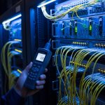
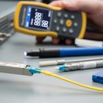
Pro Tip: In remote edge cabinets, the most expensive failures are often “works on the bench, fails in the field.” The culprit is frequently fiber budget margin plus connector cleanliness. Treat your optical budget like a design parameter, not a procurement checkbox: measure receive power in dBm after installation and verify it stays within the module’s specified sensitivity range across temperature and aging.

Key specs that decide reach, stability, and operability
Optical module selection at the edge should start with a strict mapping from your network requirement to the module’s electrical and optical parameters. Engineers often focus on “distance” alone, but stability depends on transmitter power, receiver sensitivity, link margin, and how the module behaves across its temperature range. Also confirm connector type and fiber type to avoid avoidable return loss issues. Finally, for edge reliability, prioritize modules with DOM support and clear compliance documentation.
Core parameters you must compare
- Data rate and lane structure: 10G uses different signaling than 25G/50G/100G, and QSFP/QSFP28 uses lane mapping that must match the host.
- Wavelength: SR uses 850 nm multimode; LR uses ~1310 nm single-mode; ER uses ~1550 nm. Wrong wavelength can pass simple tests but fail under real link margins.
- Reach: vendor “typical” reach is not your installed reach; you need budget using fiber attenuation plus patch cord loss.
- Optical power: Tx power range and Rx sensitivity determine margin. Ensure your measured Rx power lands inside the module’s recommended operating window.
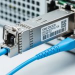
- Connector: LC vs MPO/MTP and APC vs UPC polishing affect return loss and reflections.
- Operating temperature: edge enclosures can exceed standard indoor limits; choose modules with the correct industrial or extended temperature grade.
- DOM and alarms: verify the switch can interpret DOM thresholds for Tx bias current, Rx power, and temperature.
Reference comparison table (common module families)
The table below compares typical spec points engineers use when selecting SFP/SFP+ class and QSFP28 class optics for edge links. Exact values vary by vendor, so always validate against the specific datasheet for the part number you plan to deploy.
| Module family (example) | Typical wavelength | Target reach (typ.) | Fiber type | Connector | DOM | Operating temp (typ.) | Notes for edge use |
|---|---|---|---|---|---|---|---|
| SFP+ 10G-SR | 850 nm | ~300 m (MMF) | OM3/OM4 | LC | Yes (standard DOM) | 0 to 70 C typical; industrial variants lower/higher | Sensitive to dirty connectors and inadequate MMF grade |
| SFP+ 10G-LR | 1310 nm | ~10 km (SMF) | Single-mode | LC | Yes | 0 to 70 C typical; industrial variants available | Better for longer runs; still needs clean splices |
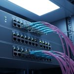
| QSFP28 25G-SR | 850 nm | ~100 m (MMF) | OM3/OM4 | MPO/MTP | Yes | 0 to 70 C typical; industrial variants available | Lane mapping and polarity critical with MPO cassettes |
| QSFP28 100G-SR4 | 850 nm | ~100 m (MMF) | OM4 preferred | MPO/MTP | Yes | 0 to 70 C typical; industrial variants available | Requires correct MPO polarity and consistent patching |
For concrete part examples, you may see modules such as Cisco SFP-10G-SR, Finisar FTLX8571D3BCL (10G-SR style), and FS.com SFP-10GSR-85 in lab and field deployments. Treat these as “families” to understand typical parameter ranges, then lock to the exact part number and datasheet for your final BOM.

Edge deployment scenario: what engineers actually face
Consider a mid-market retail edge buildout with 20 sites where each site has a 48-port 10G ToR switch and a small aggregation switch. Each site uses four uplinks to the regional PoP over single-mode fiber: roughly 6 km average distance with two patch panels and about 2 splices per path. The cabinets are in unconditioned spaces; during summer commissioning, ambient air can hit 48 C inside the enclosure, while winter nights can drop near 5 C. Engineers typically start with SFP+ 10G-LR optics because the reach comfortably covers the fiber plan, then later add higher-density 25G aggregation using QSFP28-SR for short in-cabinet runs over OM4.
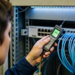
In this environment, best practices include verifying the measured receive power right after installation, not just at acceptance. If the measured Rx power is close to the module’s sensitivity limit, a later change like swapping patch cords or cleaning a connector improperly can push the link into intermittent errors. Field teams also watch DOM “temperature” and “bias current” alarms during the first 72 hours, because thermal drift can reveal marginal enclosure airflow or a module that is not rated for the real temperature profile.
Selection checklist: best practices engineers use before ordering
Use this ordered checklist to reduce rework and avoid “works in the lab” surprises. It is designed for edge optical module selection across SFP/SFP+/QSFP/QSFP28 families, including both OEM and third-party optics.
- Distance and fiber type: confirm single-mode vs multimode, and validate installed fiber grade (OM3 vs OM4) and expected attenuation.
- Connector and polarity: LC vs MPO/MTP, and MPO polarity method (where applicable) to prevent lane cross-wiring.
- Data rate and host support: ensure the switch port is configured for the correct speed and that the module form factor matches the port (SFP vs SFP+ vs QSFP28).
- Optical budget margin: compute budget using fiber attenuation plus insertion loss from patch panels, splices, and connectors; then verify against Rx sensitivity and Tx power ranges.
- DOM support and alarm compatibility: confirm DOM is enabled and that your switch firmware reads the module diagnostics correctly.
- Operating temperature grade: choose an industrial/extended temperature module if the cabinet can exceed standard ranges.
- Vendor lock-in risk: check the switch vendor’s optics compatibility list and firmware requirements to avoid “unsupported transceiver” events.
- Lead time and spares strategy: edge sites need predictable replacement availability; stock spares sized for the failure distribution over the planned lifecycle.
Decision shortcuts that prevent common misorders
- If the site uses short in-cabinet multimode runs with MPO, treat polarity and cleaning as first-order concerns.
- If the site uses longer single-mode runs, prioritize reach margin and connector/splice quality over “best price.”
- If you plan to automate monitoring, ensure the module provides DOM and that the switch supports the same threshold interpretation.
Common pitfalls and troubleshooting at the edge
Edge optics failures are often systematic. Below are concrete pitfalls, their typical root causes, and practical fixes that field engineers can apply during commissioning or remote troubleshooting.
Link flaps after cleaning “looks fine”
Root cause: connector end-face contamination that is not visible to the naked eye, or incorrect cleaning technique that leaves residue. For SR optics, this is especially common with LC and MPO connectors where dust or micro-scratches increase attenuation and reflections.
Solution: use an inspection microscope to confirm end-face cleanliness, clean with correct tools, and re-terminate if scratches are present. Re-measure Rx power and check whether the module’s DOM alarms correlate with link flaps.
Wrong module family selected due to “reach” misunderstanding
Root cause: mixing SR and LR expectations. A vendor reach headline may assume ideal test conditions (patch cord lengths, connector loss, and fiber attenuation). In edge deployments with additional patching or older fiber, the effective reach can be much shorter.
Solution: calculate an optical budget using your installed plant losses, then verify Rx power at the far end. If you are near the sensitivity edge, move to LR/ER-class optics or reduce patch cord count.
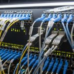
MPO polarity errors cause high error rates without obvious link-down
Root cause: MPO/MTP polarity mismatch where transmit and receive fibers are crossed for one or more lanes. The link may come up, but you see CRC errors, FEC warnings (if applicable), or intermittent performance degradation.
Solution: verify MPO polarity method in the patching plan, re-cable using the correct polarity adapters, and confirm lane mapping using switch diagnostics. Re-check optical power per lane if your platform exposes lane-level DOM.
“Unsupported transceiver” messages after firmware updates
Root cause: switch firmware tightening of optics compatibility checks, including vendor ID expectations or DOM register interpretation differences. This can happen even when the module is electrically capable.
Solution: validate against the switch vendor’s optics compatibility guidance for your exact firmware revision. If you must use third-party modules, test in a staging rack with the same switch firmware before rolling out to sites.
Cost and ROI note: what to budget beyond the module price
Typical pricing varies widely by speed and vendor, but as a planning baseline: 10G SFP+ optics often land in the range of tens of dollars for third-party modules and higher for OEM-approved parts; 25G/40G/100G QSFP/QSFP28 optics can be several times higher depending on reach and whether you choose SR vs LR/ER. The ROI driver is not only purchase cost; it is operational downtime and truck-roll frequency.
OEM optics may reduce compatibility risk with enterprise switch firmware, which can lower total cost of ownership (TCO) when failures trigger dispatches. Third-party optics can be cost-effective, but you should budget for qualification testing, extra spares, and the possibility of firmware-related incompatibility. From field experience, a single avoidable site visit due to “unsupported transceiver” can outweigh the savings on multiple modules.
FAQ
How do I confirm the right wavelength for best practices edge optics?
Start with the fiber type and your planned reach. SR typically uses 850 nm over multimode; LR/ER use 1310 nm or 1550 nm over single-mode. Then validate with the module datasheet wavelength and measure receive power after installation.
Are DOM metrics enough to predict failure in the field?
DOM helps, but it is not a complete predictive model. Temperature, bias current, and Rx power trends can indicate aging or marginal connections, but you still need connector inspection and optical budget validation. Use DOM alarms as an early warning and correlate them with error counters and link events.
What is the most common reason an edge link works on day one but degrades later?
The most frequent causes are connector cleanliness, insufficient optical margin, and thermal stress that pushes the module toward its operational limits. Even small additional insertion loss from patch cord changes can reduce margin enough to increase CRC or FEC-related errors.
Can I mix OEM and third-party optics in the same edge switch?
Often yes, but compatibility is firmware-specific. The host may enforce transceiver vendor checks, and DOM interpretation can differ. Best practice is to standardize vendors per site and validate with the switch firmware version you run in production.
What should I check if MPO-based QSFP links show high error rates?
First verify MPO polarity and lane mapping, then inspect and clean the MPO end faces. Next check Rx power and any lane-level diagnostics if available. If errors persist with correct polarity, evaluate fiber attenuation and patch panel insertion loss.
Do industrial temperature optics matter for indoor edge cabinets?
If your enclosure regularly approaches the upper range of standard optics, industrial/extended temperature modules can prevent intermittent issues. Measure ambient temperature near the module cage and plan for airflow limitations during power-saving modes or seasonal HVAC changes.
Following best practices for edge optical module selection comes down to matching standards-level compatibility, validating optical budget with real measurements, and planning for temperature and connector reality. Next, review best practices for fiber cleaning and inspection to reduce avoidable link instability caused by contamination.
Author bio: I have deployed and troubleshot SFP/SFP+ and QSFP/QSFP28 optics in edge and data center environments, using DOM telemetry and optical power measurements to isolate faults. I focus on practical compatibility checks with switch firmware and disciplined fiber plant validation for long-lifecycle reliability.