Why AOC and DAC choices can make or break data center performance
In leaf-spine and server-access networks, transceiver cabling is not a commodity detail; it directly affects latency, link margin, thermal headroom, and mean time between failures. This article helps network and facilities teams compare active optical cable (AOC) and direct attach copper (DAC) using field-ready criteria aligned with IEEE 802.3 link behavior and vendor datasheet realities. You will also get a step-by-step implementation plan, a troubleshooting checklist, and a cost and TCO lens for 25G through 400G environments.
transceiver-lifecycle-management
Prerequisites for an apples-to-apples AOC vs DAC comparison
Before you swap anything, lock the test boundaries so your results reflect real data center performance rather than mixed optics, patch cords, or firmware variance. Use the same switch models, optics types, and cabling paths for each trial; otherwise, you cannot attribute changes to AOC or DAC. Confirm that both options meet the electrical/optical interface requirements for the exact lane rate and reach class you are deploying.
What to collect
- Switch and port model numbers (for example, Cisco Nexus, Arista EOS platforms, or Broadcom-based whitebox switches) and the exact port speed configuration.
- Transceiver and cable part numbers (for example, Finisar/FS.com or OEM AOC like FTLX8571D3BCL style variants, and DAC like Cisco compatible DAC for the same speed class).
- Environmental data: inlet temperature, airflow direction, and cable bend radius constraints.
- Validation tooling: switch telemetry for CRC/BER counters, optic DOM readings, and (optionally) a fiber OTDR for AOC runs.
Expected outcome
You will have a controlled baseline where only the physical layer changes. That baseline is the foundation for a defensible performance and reliability decision.

Step-by-step: implement a controlled AOC vs DAC trial
Run a staged trial that mimics production traffic patterns and captures both performance counters and operational risk. The goal is to quantify not just “it links up,” but how stable the link is under thermal cycling and realistic utilization. Treat this like an ISO 9001 corrective action loop: define acceptance criteria, measure, compare, and document.
Choose the exact reach class and lane rate
Match the transceiver to the intended topology segment. If you are testing ToR-to-spine within 3 to 10 meters, DAC is often viable; if you need 20 to 80 meters across a structured cabling zone, AOC becomes more relevant. Use the vendor reach guidance and confirm the switch supports the specific electrical spec for that speed.
Expected outcome: You avoid unfair comparisons where one technology is outside its design envelope.
Install with identical port numbering and patching
Keep the same physical route geometry. For AOC, ensure the fiber ends are clean and the cable is not stressed at the cage bend points. For DAC, verify the connector seating and avoid exceeding the minimum bend radius; copper conductors are sensitive to mechanical stress and micro-motion.
Expected outcome: Your measurements reflect link behavior, not connector and handling artifacts.
Enable telemetry and capture counters at steady state
On the switch, poll interface counters for CRC errors, link flaps, and any optical power alarms. For AOC, read DOM metrics such as transmit power, receive power, bias current, and temperature. For DAC, you typically rely more on link error counters because some third-party DACs expose fewer DOM fields; document what is available.
Expected outcome: A baseline dataset that can be compared across runs.
Validate under load and thermal conditions
Use a realistic traffic generator (for example, iperf3 between endpoints) and run for a time window that reveals intermittent issues. In practice, 8 to 24 hours is a good starting point for early screening; for environmental confidence, run a second cycle during a different cooling regime. Track whether errors correlate with temperature drift or airflow changes.
Expected outcome: A performance picture that includes stress behavior relevant to data center performance.
Document and decide using acceptance criteria
Define pass/fail thresholds up front. A common approach is “no link flaps” plus stable error counters (for example, zero CRC spikes over the observation window) and no DOM alarms. If you deploy under a change management process, attach the trial report to the ticket for auditability.
Expected outcome: A decision that is traceable and repeatable, not subjective.

AOC vs DAC: how physics translates into data center performance
DAC uses copper signal transmission within a limited reach, while AOC converts electrical signals to optical inside the cable and sends light over fiber. In data center performance terms, AOC often improves immunity to electromagnetic interference and enables longer reach, but it introduces optical power budget constraints and DOM dependence. DAC can be lower latency and simpler in very short runs, but it is more sensitive to channel loss and mechanical handling.
Technical specifications comparison (typical, speed-dependent)
Exact values vary by vendor and part number; use this table as a starting template for your selection worksheet.
| Parameter | DAC (Direct Attach Copper) | AOC (Active Optical Cable) |
|---|---|---|
| Common data rates | 10G, 25G, 40G, 100G (varies by platform) | 10G, 25G, 40G, 100G, 200G, 400G (platform dependent) |
| Typical reach class | Up to ~5 to 7 m for many 25G/40G designs; varies by spec | ~5 to 100 m depending on wavelength and power budget |
| Wavelength / signaling | Electrical signaling over copper twinax | Optical signaling over multimode or single-mode fiber |
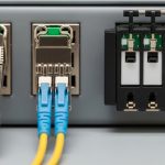
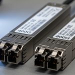
| Connector type | Integrated SFP/SFP+/QSFP style direct attach ends | Integrated QSFP/QSFP-DD style ends with embedded optics |
| Optical power budget | N/A | Critical; governed by transmit power and receive sensitivity |
| DOM and telemetry | Varies; some provide limited telemetry | Often provides DOM: temperature, bias current, TX/RX power |
| Operating temperature | Typically industrial to extended ranges; check datasheet | Typically similar ranges; check vendor and cable spec |
What to expect in real deployments
In practice, AOC can reduce “mystery errors” when EMI or grounding issues exist across long cable runs. DAC tends to be attractive for high-density racks where cable management is tight and the run length is short. IEEE 802.3 compliance and the switch vendor’s supported cabling list are still the deciding gate; even a technically capable cable can be rejected by strict compatibility rules.
Pro Tip: If your switch supports DOM-based alerting, use it as an early warning system. For AOC, a slow drift in RX power or bias current often precedes link instability after cleaning issues, airflow dust loading, or gradual connector contamination.
Selection criteria checklist for engineering decisions
Use the following ordered checklist to choose the option that best supports data center performance while minimizing operational risk. This is designed for repeatable procurement and change control.
- Distance and reach class: confirm the actual measured path length, including slack and patch panel routing.
- Switch compatibility: verify the exact module and cable part number appears in the vendor compatibility matrix for your platform and firmware.
- Signal integrity budget: for copper, account for channel loss and connector quality; for AOC, ensure power budget margin for your fiber type and expected aging.
- DOM support and observability: require telemetry fields you can monitor (especially for AOC) and verify alert thresholds.
- Operating temperature and airflow: confirm the cable’s rated temperature range and ensure airflow is not blocked by cable routing.
- Vendor lock-in risk: evaluate whether third-party options are supported and whether you can use interchangeable parts during failures.
- Maintenance workflow: prefer designs that match your cleaning, inspection, and replacement process maturity.
- Reliability evidence: review vendor MTBF claims cautiously and prefer field data from your own environment.
Expected outcome
A selection that aligns physical-layer feasibility with operational maintainability, not just “lowest cost per port.”

Real-world deployment scenario: leaf-spine with mixed run lengths
Consider a 3-tier data center leaf-spine design with 48-port 25G ToR switches feeding a pair of spines. The ToR-to-server runs average 2.5 m and are placed inside a short, dense rack environment; the ToR-to-spine patch zone uses longer structured cabling averaging 35 m with frequent moves during maintenance. In this setting, engineers often populate server-access ports with DAC for simplicity and latency, while using AOC (or AOC plus structured fiber where applicable) on the longer spine uplinks to gain interference immunity and maintain stable link margins. After a 12-hour load test at sustained throughput, the AOC uplinks show fewer CRC spikes, while the DAC downlinks show lower operational complexity when cable handling is disciplined.
Common mistakes and troubleshooting tips (top failure modes)
Even when specs look compatible, real data center performance issues usually come from mechanical, environmental, or compatibility gaps. Below are three common failure points with root causes and concrete fixes.
Failure mode 1: Link flaps after installation
Root cause: DAC connector not fully seated, or excessive bend radius causing intermittent contact and signal integrity degradation.
Solution: Reseat both ends, inspect for bent pins, and re-route to maintain minimum bend radius from the vendor datasheet. Re-run a short error counter test and confirm no link renegotiations.
Failure mode 2: AOC alarms for low RX power or rising temperature
Root cause: Fiber contamination at mating points, dust exposure during cleaning omission, or airflow blockage raising temperature.
Solution: If the AOC uses external fiber mating (some do in hybrid designs), clean using lint-free wipes and validated cleaning tools; for integrated AOC, inspect the cable ends and replace if contamination persists. Restore airflow paths and confirm rack inlet temperatures are within spec.
Failure mode 3: Persistent CRC/BER despite “link up” status
Root cause: Compatibility mismatch between the cable’s electrical/optical profile and the switch firmware expectations, or marginal power budget due to aging and patch cord differences.
Solution: Verify the exact part number is supported by the switch vendor. For AOC, compare DOM values against the known-good baseline and replace if RX power margin is insufficient. For DAC, try an alternate vendor part that is explicitly validated for the platform.
Cost and ROI note: what to budget for reliability and uptime
Pricing varies widely by speed and vendor, but a realistic budgeting approach is to compare installed cost plus expected failure and labor. In many markets, third-party DACs and AOCs cost less upfront than OEM optics, but you risk reduced observability (limited DOM), stricter compatibility failures, and higher replacement churn if your environment is harsh. For ROI, factor in labor time to swap modules, downtime risk, and the cost of troubleshooting. A small percentage reduction in error events and MTTR can outweigh a modest per-port price difference when you value uptime in terms of business continuity.
FAQ
Which is better for data center performance: AOC or DAC?
It depends on distance and environment. For short runs with disciplined cable handling, DAC can deliver strong performance with low operational overhead. For longer runs or EMI-sensitive zones, AOC often improves link stability and observability through DOM telemetry.
Do AOCs have to match fiber type like MMF vs SMF?
Yes, AOC optics are designed for specific fiber and wavelength characteristics, and the power budget depends on the channel. Use the vendor datasheet and your existing fiber plant documentation to confirm compatibility.
How do I validate performance beyond “link up”?
Collect counters for CRC errors and link flaps and, for AOC, monitor DOM values such as TX/RX power and temperature. Run load tests long enough to surface intermittent issues and compare results to a baseline.
Are third-party DACs and AOCs safe to deploy?
They can be safe, but only if your switch firmware supports them and you have evidence from your own environment. Use the switch compatibility list and require a clear return or warranty process to control TCO.
What environmental factors matter most for transceiver performance?
Airflow obstruction, inlet temperature drift, dust loading, and mechanical vibration all affect reliability. AOC also adds optical sensitivity to contamination, so cleaning discipline and connector inspection workflows matter.
How should we plan spares to reduce MTTR?
Keep spares for the exact part numbers validated by your switch platform, not just “the same speed.” If your AOC supports DOM alerts, prioritize spares for the segments showing the earliest telemetry drift.
If you want consistent data center performance, treat AOC vs DAC as an engineering system choice: match reach, confirm compatibility, monitor telemetry, and validate under realistic thermal and load conditions. Next, review transceiver-lifecycle-management to build a maintainable standards-based process for module selection, inspection, and failure response.
Author bio: I am a reliability-focused field engineer who designs and audits high-density network cabling validation for uptime-critical deployments. My work emphasizes ISO 9001 traceability, MTBF-informed spares planning, and environmental testing practices grounded in vendor specifications.