AI workloads move faster than traditional campus designs, and the wrong optics can quietly throttle your GPU fabric. This guide helps network and cabling engineers choose the right AI transceiver for leaf-spine, TOR-to-server, and high-throughput storage backplanes. You will get a practical buying plan: what to measure, what to verify in vendor compatibility lists, and how to deploy with confidence.
Prerequisites before you buy any AI transceiver
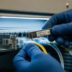
Start by inventorying your physical layer reality. In the field, I often see “it should work” assumptions fail because the switch vendor expects a specific optics family, DOM behavior, or lane mapping. Before ordering, confirm the transceiver form factor, speed, fiber type, and link budget constraints using your switch documentation and fiber test results.
Make sure you have these items ready: (1) switch model numbers and their confirmed optic compatibility guidance, (2) optics cage types (QSFP28, QSFP56, OSFP, SFP28, etc.), (3) planned distance in meters, (4) fiber type and connector style, and (5) OTDR or at least link qualification results (insertion loss and reflectance). If you are upgrading an existing AI cluster, also capture current port configuration and optics telemetry baselines.
Collect hard inputs from the rack and the fiber
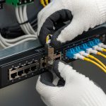
- Identify the exact port type on the switch (for example, QSFP28 cages for 25G/100G, or OSFP for 400G).
- Measure distance end-to-end including patch panels. Don’t rely on “room length”; use cable labels and a tape measure during prebuild.
- Verify fiber plant: multimode OM4 or OM5, or single-mode OS2; confirm connector type (LC/UPC, MPO/MTP polarity).
- Run fiber tests (at minimum: OLTS for loss, OTDR for troubleshooting). Record dB margin vs transceiver budget.
- Confirm temperature and airflow near the cages. Many “mystery faults” come from blocked airflow or hot aisles.
Expected outcome: You can map each switch port to a specific link spec (data rate, wavelength, reach, and connector) and avoid buying optics that cannot meet your loss and environmental constraints.

Match AI transceiver optics to link distance, fiber type, and wavelength
The most common selection mistake is choosing optics by “speed only.” AI fabrics typically use short-reach multimode, but some campus extensions or storage backhaul demand single-mode. Your transceiver family must align with the fiber plant: OM4/OM5 with SR optics, or OS2 with LR/ER optics. Also confirm whether you need duplex LC or parallel MPO/MTP connectors for higher-density lanes.
Know the typical AI optics categories
- SR (short reach) for multimode: often 850 nm class for 25G/50G/100G style optics, depending on module generation.
- DR (data center reach) can be single-mode 1310 nm class in some families.
- LR for longer single-mode (commonly 1310 nm), and ER for extended reach.
- FR variants exist for specific vendor implementations.
For AI transceivers, also pay attention to whether you are buying 100G/200G/400G “pluggables” that use multiple lanes. Lane count and ordering matter for correct optics and switch mapping.
Technical specifications table (what to compare before purchase)
Use this table as a baseline comparison when you evaluate candidate optics. Exact values vary by vendor and part number, so always verify against the specific datasheet you plan to buy.
| Optics type | Typical wavelength | Typical reach class | Fiber type | Connector | DOM support | Operating temp (typical) |
|---|---|---|---|---|---|---|
| SR (multimode) | 850 nm class | ~100 m to ~300 m | OM4 / OM5 | LC (or MPO/MTP for high density) | Usually supported | 0 to 70 C or -5 to 85 C |
| DR / LR (single-mode) | 1310 nm class | ~500 m to ~10 km | OS2 | LC | Usually supported | 0 to 70 C or -5 to 85 C |
| ER (extended single-mode) | 1550 nm class | ~10 km to 40 km | OS2 | LC | Often supported | -5 to 85 C (commonly) |
Expected outcome: You can narrow candidates to only those optics whose wavelength and reach class fit your fiber type and measured loss margin.
Verify switch compatibility, DOM telemetry, and power behavior
AI transceivers are not just “optical pipes.” Switch vendors implement compatibility rules that can include EEPROM identification, DOM thresholds, and power budgeting. In practice, I have seen ports refuse to bring up links when the transceiver’s DOM details don’t match what the platform expects, even if the optics are electrically capable.
Check compatibility lists and lane mapping
Before ordering, cross-check your switch model against the optics support matrix. For example, Cisco publishes compatibility guidance for modules such as Cisco SFP-10G-SR for 10G-SR use cases, and similar guidance exists for QSFP28/QSFP56/OSFP families. For 400G-class optics, confirm whether the switch uses a specific breakout or lane alignment method.
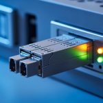
On the optics side, verify that the module supports DMI/DOM (Digital Diagnostic Monitoring) and that the switch can read and act on alarms. Many platforms use DOM to log temperature, laser bias current, received power, and TX/RX power. If you plan to integrate telemetry into your monitoring stack, confirm field names and thresholds from the vendor datasheet.
Validate power and thermal constraints
AI clusters run dense. A transceiver that technically meets reach may still fail operationally if it overheats. Confirm module power draw (often in the datasheet as maximum mW) and ensure airflow meets the vendor’s requirement. If you are upgrading line cards, confirm whether the switch has sufficient power headroom per port or per line card.
Pro Tip: In many deployments, the biggest “works on bench, fails in rack” issue is DOM alarm thresholds. A third-party AI transceiver may report valid optical power but a different temperature or bias-current scaling, triggering the switch to administratively disable the port. Always test in a staging rack with the same airflow and power budget, then confirm DOM readings in the switch CLI before scaling out.
Expected outcome: Your selected AI transceivers will be recognized by the switch, telemetry will be readable, and link bring-up will be stable under real rack thermal conditions.

Choose the right module family: speed, form factor, and optics vendor strategy
AI transceivers come in multiple form factors and speed grades, and the compatibility surface area grows with density. For example, QSFP56 optics are common in 400G architectures, while OSFP is often used for similar high-density 400G/800G style systems. Your decision should consider not only reach and wavelength, but also operational reliability, lead times, and whether you can standardize across vendors.
Selection criteria and decision checklist (engineers use this order)
- Distance: measured end-to-end length plus patch panel and connector loss; include safety margin (commonly 1 to 3 dB depending on your design practice).
- Fiber type: OM4 vs OM5 for multimode; OS2 for single-mode; confirm polarity and MPO/MTP cleaning requirements.
- Switch compatibility: match the exact switch model to the optics support matrix; confirm form factor and lane mapping.
- DOM support: ensure DOM works with your platform; confirm alarm thresholds and monitoring integration needs.
- Operating temperature: pick modules with the correct industrial or extended temperature rating for your aisle conditions.
- Budget and TCO: include total cost of ownership, not just unit price; consider failure rates and warranty coverage.
- Vendor lock-in risk: decide whether you will standardize on OEM optics or use vetted third-party models across the entire fabric.
- Supply chain resilience: confirm lead times and multiple sourcing options for the exact part number.
Expected outcome: You can justify each purchase decision with measurable inputs and compatibility evidence, reducing late-stage surprises.
Concrete examples of part families to look up
When you research, you will often encounter models like Finisar FTLX8571D3BCL for specific SR use cases (verify exact reach and speed class in the datasheet). For Cisco-based environments, you may see part numbers similar to Cisco SFP-10G-SR depending on generation. For third-party sourcing, providers like FS.com list modules such as FS.com SFP-10GSR-85 for 10G-SR style deployments. Treat these as starting points for datasheet verification, not as universal substitutes.
Expected outcome: Your shortlist becomes vendor-accurate and datasheet-driven, not guesswork.

Step-by-step implementation plan for deploying AI transceivers
This section turns buying into a controlled rollout. Use it when you are expanding an AI cluster, upgrading from older 25G/100G links, or standardizing optics across multiple racks.
Prerequisites checklist for rollout
- You have the switch model, port type, and the optics compatibility matrix for that exact platform.
- You have fiber test results with measured loss and reflectance, and you know connector types and polarity.
- You have a staging rack with the same switch/line card model and airflow characteristics.
- You have monitoring ready for DOM and link state alarms.
Build a per-port optics plan
- Create a spreadsheet mapping each switch port to: transceiver part number, fiber type, connector type, and expected reach.
- Include a margin note such as: “measured loss 1.8 dB, transceiver budget per datasheet X dB, planned safety margin Y dB.”
- Tag each fiber patch run with MPO/MTP polarity verification status if applicable.
Expected outcome: You can order and stage modules without ambiguity and without swapping optics mid-install.
Stage test in a controlled rack
- Install a small batch (for example, 4 to 8 ports across at least two line cards).
- Bring up links and verify DOM telemetry in the switch UI/CLI.
- Confirm that link speed locks to the expected rate and that there are no repeating optical warnings.
Expected outcome: You validate compatibility, DOM behavior, and thermal stability before scaling.
Validate link performance with test traffic
- Run traffic that resembles AI patterns (for example, east-west flows with sustained throughput) for at least 30 to 60 minutes.
- Monitor interface counters: CRC errors, FCS errors, and link flaps.
- Compare DOM optical power readings at idle and under load.
Expected outcome: You confirm stability, not just link-up.
Document and standardize
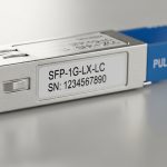
- Record transceiver serial numbers if your warranty process requires it.
- Update your change management record with measured fiber loss and final operational settings.
- Standardize cleaning and polarity procedures for MPO/MTP runs and attach them to your install checklist.
Expected outcome: You reduce mean time to repair (MTTR) during future incidents.
Common mistakes and troubleshooting tips for AI transceiver issues
When AI transceivers fail, the symptoms are often misleading: link down, flapping, or degraded performance without obvious errors. Below are the top failure modes I see in real deployments, with root cause and fast fixes.
Failure point 1: Link does not come up after insertion
Root cause: Switch compatibility mismatch or unsupported transceiver EEPROM identity for that platform/port. Sometimes the module is electrically fine but not recognized in the vendor’s compatibility logic.
Solution: Confirm the exact switch model and port type against the optics support matrix. Try the same transceiver in a known-compatible port. If available, test an OEM optic to isolate whether the issue is compatibility vs fiber.
Failure point 2: Link flaps under load or during temperature changes
Root cause: Thermal constraints or marginal optical budget due to dirty connectors, excessive patch loss, or fiber stress. In MPO/MTP systems, polarity mistakes can also cause intermittent behavior.
Solution: Inspect and clean connectors using proper lint-free methods and IPA where allowed by site policy. Re-test with an optical power meter and verify polarity. Improve airflow or reseat modules to ensure proper contact pressure.
Failure point 3: DOM alarms show warnings, then the port disables
Root cause: DOM threshold mismatch, inaccurate calibration, or a platform expecting a specific DOM behavior. This can happen with some third-party optics even when the vendor claims compatibility.
Solution: Compare DOM readings from the staging rack with platform expectations and vendor documentation. If you can, adjust monitoring thresholds only if your platform policy allows it; otherwise replace optics with a module explicitly validated for your switch and firmware version.
Cost and ROI note: what you actually pay for with an AI transceiver
Unit price is only one part of the TCO. OEM optics often cost more, but they usually reduce compatibility risk and speed up RMA resolution. Third-party optics can be significantly cheaper, yet you must factor engineering time spent validating DOM behavior, staging tests, and potential warranty complications.
In many data center purchasing cycles, 100G-class optics and 400G-class pluggables can range from roughly $150 to $600 per module depending on speed, reach, and whether it is OEM vs third-party. For budgeting, include the cost of fiber cleaning supplies, spare optics for critical links, and the labor time for staging validation. ROI typically comes from minimizing downtime and avoiding re-cabling or port swaps caused by incompatibility.
Expected outcome: You can justify an optics strategy that balances procurement cost with operational reliability.
FAQ
What is an AI transceiver, and how is it different from normal optics?
An AI transceiver is a high-performance pluggable optic used in AI clusters and high-throughput fabrics. It differs mainly in speed class, density, and the operational expectations for DOM telemetry, compatibility, and thermal behavior on modern switch platforms. The key is matching the module to your switch and fiber plant.
Should I buy OEM optics or third-party modules?
OEM optics reduce compatibility and support friction, which matters during scale-out. Third-party modules can be cost-effective if you validate them in a staging rack and ensure DOM and thresholds behave correctly. The best choice depends on your risk tolerance, warranty process, and lead-time requirements.
How do I calculate whether my link budget supports the chosen reach?
Use measured fiber loss from OLTS/OTDR, then compare against the transceiver’s datasheet optical budget for the exact module. Add connector and patch panel loss, and keep a safety margin for aging and cleaning variability. If you cannot measure, do not guess—retest before deployment.
What DOM telemetry should I monitor during rollout?
Monitor laser bias current, module temperature, transmit power, and received power. Also watch for switch-reported optical warnings, link flaps, and any interface counters indicating degraded signal quality. Capture baselines during idle and under load so you can detect drift later.
Why do some optics work on the bench but fail in production?
Bench setups often have better airflow, cleaner connectors, shorter patch paths, and different power budgets. Production racks add thermal stress, cable stress, and real patch panel loss. Always stage-test in an environment that matches airflow and wiring practices.
Which standards should I reference when selecting an AI transceiver?
Reference IEEE 802.3 for Ethernet physical layer guidance, plus vendor datasheets for the specific transceiver and optics family. For cabling infrastructure, use ANSI/TIA recommendations for fiber testing and performance verification. Then rely on your switch vendor compatibility matrix for the final acceptance criteria.
If you want the fastest path to a stable rollout, start with your fiber measurements and the switch compatibility matrix, then validate DOM behavior in a staging rack. Next, align your optics selection to distance and fiber type using the checklist above via fiber link budget and testing workflow.
Author bio: A veteran network admin specializing in routing, switching, fiber cabling, VLAN edge design, and high-speed optics troubleshooting across AI and data center fabrics. I have deployed and validated pluggable optics in production with measurable link budgets, DOM telemetry checks, and failure-mode playbooks.