AI network adaptation: choosing transceivers for future computing needs
In modern racks, traffic patterns shift hourly as inference batches, training jobs, and caching workloads move across the fabric. That is where AI network adaptation becomes practical: selecting the right optical transceivers so your switches can scale bandwidth and maintain link stability as requirements change. This article helps network engineers and field technicians choose optics by distance, interface behavior, and operational constraints, using concrete compatibility and troubleshooting points.
Why AI network adaptation stresses optics and link behavior
AI workloads often create bursty, short-flow traffic that can exceed baseline utilization, pushing leaf-spine links into higher average throughput and higher burst peaks. In Ethernet terms, that means more frequent link renegotiation events during reboots, more sensitivity to marginal optical budgets, and more error-rate headroom needed for forward error correction and receiver linearity. The optics you pick must support the switch’s electrical interface (for example, SR optics on QSFP+ 10G or SR4 on 100G), while also meeting vendor-specific expectations for diagnostics and DOM reporting.
From a field perspective, “adaptation” usually shows up as mixed generations: a new AI cluster with 400G or 800G cores added alongside existing 10G and 25G access. You want transceivers that can handle the new traffic profiles without introducing silent degradations like elevated BER, CRC spikes, or intermittent link flaps. IEEE 802.3 defines the physical layer behavior for Ethernet, but the real-world outcomes depend heavily on transceiver datasheets and the host switch’s optics implementation. Source: IEEE 802.3
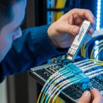
Pro Tip: During staged rollouts, validate optics with a calibrated optical power meter and a BER test plan, not just link-up. Many “works on the bench” modules fail under rack temperature swings because the transmitter bias current and receiver sensitivity drift together.
Transceiver selection fundamentals for AI-ready fabrics
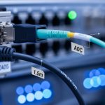
Start with the transport layer you actually run: 10G, 25G, 40G, 100G, 200G, 400G, or 800G. Then map it to fiber type and distance using the optical budget and link budget rules in the module datasheet, plus your patch-cord losses and MPO/MTP cleaning quality. For short-reach deployments, common choices include multimode fiber using 850 nm optics (OM4/OM5), and single-mode using 1310 nm or 1550 nm depending on reach requirements.
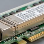
Also confirm connector standard and lane count. For instance, 100G SR typically uses four lanes (SR4) in a QSFP28 form factor, while 400G SR8 uses eight lanes in QSFP-DD. If you mismatch lane expectations or the switch port wiring mode, you can get link instability that looks like “random” drops. Finally, verify DOM support because many AI fabrics rely on telemetry for proactive replacement and optics health alarms.
Key specifications that matter in practice
Engineers often compare only reach. In AI network adaptation, you should compare wavelength, data rate, reach, connector type, typical optical power, receiver sensitivity, DOM format, and operating temperature range. These determine whether a module stays within the optical budget across patch cords, bend losses, and thermal conditions.
| Transceiver type | Data rate | Wavelength | Reach (typ.) | Fiber / connector | Form factor | DOM & temp |
|---|---|---|---|---|---|---|
| Cisco SFP-10G-SR | 10G | 850 nm | ~300 m (MM) | OM3/OM4, LC | SFP+ | DOM: yes; Operating temp typically commercial/industrial variants |
| Finisar FTLX8571D3BCL (example 10G SR) | 10G | 850 nm | ~300 m (MM) | OM3/OM4, LC | SFP+ | DOM support varies by exact SKU; check datasheet |
| FS.com SFP-10GSR-85 (example 10G SR) | 10G | 850 nm | ~300 m (MM) | OM4, LC | SFP+ | DOM varies by product line; confirm DOM and temp grade |
| Typical 100G SR4 (QSFP28) | 100G | 850 nm | ~100 m (MM, OM4) | OM4/OM5, MPO | QSFP28 | DOM: yes on most modern modules; temp grade varies |
Deployment scenario: adapting links during an AI cluster expansion
Consider a 3-tier data center leaf-spine topology with 48-port 10G ToR switches feeding 25G uplinks to a spine tier, then an AI expansion adds GPU servers that generate sustained east-west traffic. In month one, you run 10G access with 300 m SR optics on OM4, averaging 35% utilization. In month two, you reconfigure uplinks to 25G and add new leaf pairs, pushing the uplink utilization to 60–75% during training bursts while keeping access mostly stable.
In this environment, AI network adaptation means optics must remain reliable at higher utilization and in higher-temperature zones near GPU racks. You should design for a margin: if your SR link budget allows 300 m, plan patch cords and splices for maybe 200–240 m effective in the “hot aisle” pathway, especially after repeated moves. Field practice: I’ve seen teams meet spec on paper, then see CRC spikes after a patch-cord re-seat because MPO endfaces were not cleaned with lint-free wipes and isopropyl at the right concentration.

Decision checklist for engineers buying optics under adaptation pressure
Use this ordered checklist when the network must adapt quickly without surprises. It is written for procurement and validation teams who need fewer returns and fewer late-night link flaps.
- Distance and fiber type: compute worst-case link distance including patch cords, splitters (if any), and connector loss; verify OM4 vs OM5 assumptions.
- Data rate and lane mapping: confirm the switch port supports the exact transceiver type (SFP+, QSFP+, QSFP28, QSFP-DD) and lane mode (SR4, SR8).
- Optical budget and receive power margin: compare module transmitter power and receiver sensitivity from the datasheet; include aging margin if the vendor provides it.
- Switch compatibility and optics policy: check the switch vendor’s transceiver compatibility list; some platforms enforce vendor or firmware-specific behavior.
- DOM support and telemetry format: ensure DOM reads (temperature, voltage, bias current, received power) are recognized by the switch or monitoring stack.
- Operating temperature range: validate modules meet the enclosure thermal profile; GPU aisles can see sustained higher ambient.
- Vendor lock-in risk: weigh OEM modules (lower integration risk) versus third-party modules (often cheaper) and confirm DOM and alarm thresholds.
Common pitfalls and troubleshooting tips during AI network adaptation
Even strong optics can fail if installation and expectations are off. Here are concrete failure modes I’ve seen, with root cause and fixes you can apply quickly.
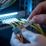
Link flaps that correlate with re-seating patch cords
Root cause: contaminated LC or MPO endfaces cause intermittent reflections and reduced receiver sensitivity, which becomes visible when utilization rises and error correction margins tighten. Solution: clean connectors with a proper fiber cleaning tool, inspect with a microscope, replace patch cords if scratches are present, and verify polarity for single-lane links.
High CRC errors or rising BER after thermal changes
Root cause: modules running outside their effective thermal envelope, or marginal optical margin that only breaks at higher ambient. Solution: measure ambient temperature at the cage, confirm module temp grade, and re-check link budget including patch cord loss; then run BER tests while monitoring interface counters.
“Module not supported” or missing DOM telemetry
Root cause: DOM pages not compatible with the switch’s expected diagnostics, or an optics policy that rejects certain vendors/firmware revisions. Solution: verify the exact part number against the switch compatibility list, update switch firmware if allowed, and confirm the transceiver’s standard compliance and DOM implementation in the datasheet.
Lane mismatch causing partial links to fail
Root cause: incorrect breakout mode or incompatible transceiver type for the port (for example, using a QSFP-DD module in a port expecting a different lane mapping). Solution: confirm port breakout configuration, consult the switch hardware guide, and validate that all lanes report “up” before declaring success.

Cost and ROI: how to budget without sacrificing reliability
In many enterprises, OEM optics price can be roughly 1.5x to 3x third-party pricing for equivalent reach and speed, depending on platform and volume. However, the ROI is not only purchase price: OEM modules often reduce integration risk, faster RMA turnaround, and fewer “works intermittently” incidents that consume engineer time. A realistic TCO model includes labor for validation, downtime risk, and the cost of repeated connector cleaning and patch-cord replacement after failures.
For AI network adaptation, I recommend budgeting spares based on failure history and environment. If you have hundreds of GPU-connected ports, even a 1–2% field failure rate can produce noticeable operational overhead during peak training windows. Third-party optics can be cost-effective, but only when compatibility lists, DOM telemetry behavior, and operating temperature grades are verified before rollout. Source: Cisco Support and optics guidance
FAQ
How do I verify AI network adaptation readiness before production?
Run a staged validation: check link-up, then confirm DOM reads and interface counters under load. Use BER testing where possible, and repeat tests after thermal cycling or after any patch-cord re-seat. This catches marginal optical margins that only fail under real rack conditions.
Can I mix OEM and third-party optics in the same switch?
Often yes, but behavior can differ by platform, especially for DOM alarm thresholds and optics policy enforcement. Always validate against the switch vendor compatibility list and confirm monitoring visibility. If you cannot see DOM telemetry, you lose early warning during adaptation events.
What fiber should I choose for AI clusters: OM4 or OM5?
For most short-reach 850 nm deployments, OM4 is common and works well up to the specified distance. OM5 can offer improved bandwidth over multiple wavelengths in certain systems, but you must match the transceiver design to the fiber capability and confirm reach assumptions in the datasheet. If you already have OM4 installed, spend first on patch quality and cleaning workflow.
Why do I see CRC errors even when the link stays up?
CRC errors indicate frame integrity problems, which can come from marginal optical power, connector contamination, or receiver sensitivity drift. Check DOM received power trends, inspect connectors, and compare error counters before and after any thermal change. Then re-run BER tests to confirm whether errors are optical or electrical.
Do I need DOM support for AI network adaptation?
DOM is strongly recommended because it enables telemetry-driven maintenance. With received power and transceiver temperature trends, you can predict degradation and schedule replacements before failures during peak training. Some monitoring stacks also correlate DOM alarms to interface counter spikes for faster root-cause analysis.