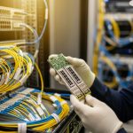
In busy data centers, optics upgrades often collide with downtime windows, switch compatibility quirks, and unpredictable reach needs. This article helps network and facilities teams evaluate adaptive transceivers so you can standardize optics today while staying ready for higher speeds and different fiber plants tomorrow. You will get practical selection checklists, a real deployment scenario, and troubleshooting notes from field-style operations.
Why adaptive transceivers matter when your fiber plan changes
Modern networks rarely stay static. A 10G leaf-spine build may later expand to 25G or 100G, and the fiber plant may include a mix of OM3, OM4, and OS2 runs with patch-panel remapping over time. Adaptive transceivers are designed to reduce the “buy once, regret later” cycle by supporting multiple operating modes (for example, different speeds and reach profiles) within the constraints of the transceiver family and the host switch.
From an engineering perspective, the key value is operational flexibility: you can align transceiver selection to real measured link conditions such as received optical power, link margin, and negotiated data rate. Most deployments still rely on IEEE 802.3 auto-negotiation behavior at the electrical layer (where applicable) and vendor-defined optics control models at the optical layer. That said, compatibility is not automatic across every switch vendor and every transceiver brand, so you must verify DOM fields and supported interface modes.
What “adaptive” usually means in optics procurement
In practice, adaptive transceivers typically fall into one or more categories:
- Multi-rate capability: supports several line rates (for example, 10G/1G or 25G/10G) depending on model.
- Reach adaptation: supports short-reach and longer-reach optics variants using different wavelengths or modulation settings.
- Configurable optics behavior: vendor options or firmware profiles that tune for link margin targets.
When you standardize on these, you reduce the number of SKUs in the spares cage and simplify change management during expansions.

Key specs that decide whether adaptive transceivers will actually work
Before you trust “adaptive” marketing, confirm the exact optics class, connector type, and power budget. Your host switch expects a specific electrical interface, and your cabling plant dictates the optical budget. The IEEE 802.3 family covers Ethernet physical layers, but the operational reality is spelled out in vendor datasheets and the switch optics compatibility matrix.
Below is a practical comparison of representative modules teams commonly mix in real racks. These are example models; always select the exact SKU that matches your switch and fiber type.
| Module type | Example model | Data rate | Wavelength | Reach (typical) | Connector | DOM / diagnostics | Operating temp |
|---|---|---|---|---|---|---|---|
| 10G SR (multimode) | Cisco SFP-10G-SR | 10.3125 Gb/s | 850 nm | 300 m OM3 / 400 m OM4 | LC | Supported (vendor-defined) | 0 to 70 C (varies by vendor) |
| 10G SR (multimode, third-party) | FS.com SFP-10GSR-85 | 10.3125 Gb/s | 850 nm | 300 m OM3 / 400 m OM4 | LC | Supported (check datasheet) | -5 to 70 C (example spec) |
| 25G SR (multimode) | Finisar FTLX8571D3BCL | 25.78125 Gb/s | 850 nm | 70 m OM4 (typical for this class) | LC | Supported (check DOM fields) | 0 to 70 C (typical) |
| 100G LR4 (single-mode) | Common vendor class (example) | 103.125 Gb/s | ~1310 nm | 10 km class | LC | Supported (check) | -5 to 70 C (typical) |
Notice the pattern: optics selection is mostly about wavelength and reach class, but “adaptive” adds the layer that the transceiver can operate across multiple modes. You still need to match the physical layer expectations of the host switch and the fiber plant. For standards context, review IEEE 802.3 for the relevant PHY definitions and vendor datasheets for optical power and receiver sensitivity. [Source: IEEE 802.3 Ethernet standards overview at IEEE]
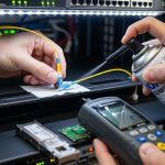
Pro Tip: In the field, “it links at first plug-in” is not the same as “it will pass every traffic condition for the next six months.” Always validate with real traffic (at least a few hours of sustained line-rate bursts) and confirm DOM-reported receive power and temperature stay inside the vendor’s guaranteed range. Many intermittent faults are margin-related, not outright incompatibility.
Real deployment scenario: adaptive optics during a 10G to 25G expansion
In a 3-tier data center leaf-spine topology, a team ran 48-port 10G ToR switches connecting to a spine fabric with 12 x 10G uplinks per ToR. The fiber plant was mostly OM4, but patching over time created a mix of shorter and longer runs, with occasional remaps to different patch rows. When the business demanded a phased move toward 25G, the team avoided a forklift upgrade by using adaptive transceivers where the host switch supported the multi-rate behavior and the vendor validated compatibility.
Operationally, they measured link behavior during cutovers: they verified DOM receive power stayed within a safe margin band (for example, not hovering near the lower end of the receiver sensitivity curve) and confirmed that temperatures remained stable under sustained load. They also standardized connector cleanliness procedures because even “working” links can degrade when dust reduces optical throughput. The result was fewer SKU swaps during expansion: the spares list shrank, and change windows stayed within the planned maintenance window because the optics selection process became repeatable.

Selection criteria checklist for adaptive transceivers in production
Use this ordered checklist when you are selecting adaptive transceivers for a real network build. The goal is not just to “get a link,” but to reduce operational risk and avoid expensive rework during expansions.
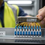
- Distance and fiber type: confirm OM3/OM4/OS2, patch loss, and worst-case run length. Use OTDR or at least validated link loss measurements.
- Switch compatibility: verify the module is supported in the exact switch model and firmware version. Many platforms maintain an optics compatibility list; check vendor guidance.
- Data rate and lane mapping: ensure the transceiver supports the required PHY mode for the target speed. For higher speeds, lane alignment matters.
- DOM support and monitoring: confirm which DOM fields are exposed (rx power, tx bias, temperature, vendor ID). Your NMS may alert on specific thresholds.
- Operating temperature and airflow: compare transceiver temperature range to your rack thermal profile. Confirm airflow direction matches vendor assumptions.
- Vendor lock-in risk: evaluate whether third-party modules are consistently accepted. If you plan long-term spares, test at least one vendor besides the primary supplier.
- Warranty and RMA throughput: confirm expected replacement timelines and whether the vendor provides batch-level traceability.
For standards and interoperability context, IEEE 802.3 defines Ethernet PHY behavior while vendor datasheets define the optics electrical and optical parameters that determine link margin. Consult vendor documentation for the most accurate constraints. [Source: IEEE 802.3 overview at IEEE]
Common pitfalls and troubleshooting steps that save hours
Even experienced teams get burned when adaptive transceivers meet real cabling plants. Here are failure modes you can recognize quickly, with root cause and a practical fix.
Pitfall 1: Links come up, then flap under traffic
Root cause: optical margin is too tight due to excess patch loss, dirty connectors, or a fiber type mismatch (for example, using OM3-rated optics on a marginal OM4 run with added splice loss). Adaptive capability may still link at low load, then fail at sustained bursts.
Solution: clean connectors with approved methods, inspect end faces under magnification, and re-measure received power using DOM. If rx power is near the lower limit, shorten the patch path or replace the fiber segment.
Pitfall 2: “Incompatible module” errors after firmware changes
Root cause: switch firmware updates can tighten optics validation rules or change how it interprets DOM fields. Some adaptive transceivers may advertise capabilities differently than the switch expects, especially across multi-rate modes.
Solution: confirm the switch firmware version and re-validate module acceptance. If supported, standardize on transceiver firmware profiles or use the vendor-recommended module family for that switch generation.
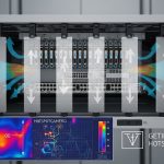
Pitfall 3: Temperature-related performance drops in high-density racks
Root cause: poor airflow, blocked vents, or overpacked cages can push transceivers beyond their guaranteed operating temperature. The system may still negotiate, but error rates rise and become intermittent.
Solution: check rack airflow direction, verify blanking panels are installed, and monitor DOM temperature. If temps exceed expected values, improve cooling or move the optics to a better-ventilated lane.
Pitfall 4: Wrong connector type or adapter stack losses
Root cause: using LC adapters with unexpected geometry, long jumper assemblies, or too many inline couplers can add insertion loss and reflection. This is common during re-cabling and patch-row rework.
Solution: audit the adapter path end-to-end. Replace the adapter stack with the simplest verified configuration and re-check link stability.
Cost and ROI: where adaptive transceivers pay off
Pricing varies by speed class, vendor, and whether you buy OEM-branded optics or third-party equivalents. As a rough field estimate, 10G SR optics often land in the low tens of dollars for third-party modules and higher for OEM options, while 25G and 100G optics can move into much higher price bands depending on reach and modulation type. Your total cost of ownership (TCO) depends on not only purchase price, but also failure rates, RMA logistics, inventory carrying costs, and downtime risk.
Where adaptive transceivers typically improve ROI is inventory consolidation. If you reduce the number of SKUs you store for different speeds and reach profiles, you cut both procurement overhead and emergency swap complexity. However, do not assume “adaptive” eliminates compatibility validation—plan a pilot phase and keep at least one known-good backup SKU during early rollout.

FAQ about adaptive transceivers for data centers
Are adaptive transceivers compatible with any switch?
No. Compatibility depends on the switch model, firmware version, and the transceiver family’s supported interface modes and DOM fields. Always verify against the switch vendor’s optics support guidance and test in a staging environment.
Do adaptive transceivers reduce fiber cabling changes?
They can, especially when the main problem is speed migration or partial reach variability. But they cannot fix a fundamentally wrong fiber type or an excessive loss budget. Measure link loss and received power to confirm the cabling plant is within spec.
What should we monitor with DOM in daily operations?
Track rx power, tx bias (or equivalent laser current indicators), and temperature. Alert thresholds should reflect vendor guidance and your observed baseline after installation and cleaning.
What is the safest way to pilot adaptive transceivers?
Start with a limited number of ports in a non-critical segment. Run sustained traffic tests and monitor DOM for at least a few hours, then extend to a longer window if possible. Keep a known-good OEM or previously validated module available for fast rollback.
Are third-party adaptive transceivers a good idea?
They can be cost-effective, but you must validate acceptance and long-term stability. The biggest risk is inconsistent vendor behavior across firmware updates or varying DOM interpretation by the switch.
How do we validate reach margin without guessing?
Use measured link loss from fiber testing tools and compare to the transceiver’s power budget and receiver sensitivity. Then confirm with DOM rx power readings under real traffic. If margins are tight, shorten the path or improve the patch configuration.
If you want the smoothest upgrades, treat adaptive transceivers as a controlled standard, not a wildcard purchase. Next, map your current optics inventory and fiber loss budget using related topic:optical budget planning for data centers.
Author bio: I build and troubleshoot production network optics in real racks, focusing on link margin validation, DOM monitoring, and repeatable change management. I document what actually breaks, what fixes it fast, and how to keep spares and compatibility aligned across upgrades.