When fiber capacity becomes the bottleneck in a modern rack-and-spine data center, the access and distribution layer design matters as much as uplinks. This article helps network and infrastructure engineers choose between active and passive optical network approaches for data center solutions, focusing on operational risk, optics compatibility, and measurable rollout steps. You will get a step-by-step implementation plan, spec comparisons, and troubleshooting patterns that match real deployments.
Prerequisites before choosing active or passive optics
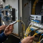
Before you compare active and passive optical network solutions, inventory your physical plant and current switching plan. Confirm whether the transceivers you use today (for example, Cisco SFP-10G-SR or third-party FS.com SFP-10GSR-85) require vendor-specific DOM behavior, and verify your power budget and connector cleanliness standards. Also decide whether you need strict determinism for latency-sensitive east-west traffic or whether the primary goal is scalable bandwidth to aggregation.
Validate these inputs (field checklist)
- Distance map: rack-to-aggregation, aggregation-to-core, and any campus extension segments in meters and estimated splice counts.
- Fiber type: OS2 or OM4/OM5, plus expected worst-case link budget margin.
- Connector plan: APC vs UPC, and whether you standardize on LC/SC in patch panels.
- Switch compatibility: confirm optics support, especially if you use vendor-locked optics with strict DOM parsing.
- Power and cooling envelope: active optics consumption per port, plus cabinet thermal constraints.
Expected outcome: you can model reach and power budgets and avoid designing around an optics or connector constraint that will later block rollout.

Step-by-step implementation: decide active vs passive for your data center solutions
Start with architecture goals, then map them to operational tradeoffs. In general, active optical solutions place electronics closer to the fiber edge for grooming, monitoring, and regeneration; passive optical network solutions rely on splitters/combiner components with fewer powered devices in the field. Your decision should be driven by latency determinism needs, fault isolation strategy, and the cost of maintenance labor over the expected lifecycle.
Define the traffic and failure model
Classify traffic patterns: east-west storage replication, north-south client access, and any overlay control-plane traffic. Determine whether your operations team needs per-client optical power telemetry and per-port diagnostics. For example, in a 3-tier leaf-spine fabric with ToR switches feeding a storage aggregation layer, you may require fast fault localization to avoid multi-rack outages.
Expected outcome: a short list of requirements such as “sub-second restoration,” “per-branch monitoring,” and “maximum allowable service disruption.”
Calculate reach and optical budget for both options
For passive splitter designs, the dominant loss elements are splitter insertion loss, patching loss, and splice/connector loss. For active designs, budget both link loss and the active device’s optical input/output sensitivity and transmit power levels. Use a worst-case link budget with conservative margins; do not assume ideal cleaning or perfect patch cord loss.
Expected outcome: a reach envelope for OM4/OM5 or OS2 that proves whether you can meet your target distance with margin.
Map operational tooling to the chosen architecture
Active optics typically expose more telemetry through DOM (Digital Optical Monitoring) and vendor telemetry, which can integrate into your monitoring stack. Passive approaches reduce powered devices but can make troubleshooting slower because the splitter obscures which branch is at fault unless you add measurement points. If your NOC uses structured alarms and automated correlation, active solutions often reduce mean time to repair.
Expected outcome: a maintenance workflow that your team can actually run during an incident.
Select transceiver and connector standards early
Even if you choose passive splitters, your transceivers must still meet the relevant Ethernet PHY requirements. For short-reach data center optics, common standards include IEEE 802.3 for Ethernet and vendor datasheets for optics parameters. If you plan to mix OEM and third-party optics, confirm compatibility behavior for DOM thresholds, especially for link bring-up and alarm states.
Expected outcome: a validated optics matrix and a connector standard that minimizes field variability.
Pilot with one row and one service class
Roll out a pilot in a single row of racks with controlled fiber paths and a defined service class, such as a single storage cluster or a single tenant VLAN. Measure link stability, optical power readings, and restoration time after induced faults like a single patch cord swap. Use the pilot to confirm whether your monitoring and change-management processes can handle the chosen architecture without surprise operational overhead.
Expected outcome: empirical metrics that support a broader rollout decision.
Active vs passive optical network solutions: what changes in practice
Active and passive approaches both move light across fiber, but they differ in where electronics and monitoring intelligence live. Active systems can regenerate or groom signals near the edge, often enabling more granular telemetry. Passive systems use splitters with fewer powered components, which can reduce energy and simplify certain maintenance tasks.
Key spec comparison (engineering view)
The table below focuses on practical parameters you will check during design reviews. Values vary by vendor and transceiver type, so treat this as a design template rather than a guarantee.
| Parameter | Active Optical Approach (typical) | Passive Optical Network Approach (typical) |
|---|---|---|
| Optical element type | Electronics-based device near edge (mux/demux, grooming, regeneration, monitoring) | Optical splitter/combiner with no active power in the field |
| Telemetry granularity | Often per-port with DOM and device telemetry integration | Limited unless you add measurement points; splitter hides branch-specific faults |
| Power consumption | Higher due to active modules and management controllers | Lower because splitters are passive |
| Insertion loss contributors | Device optics plus connector/splice losses | Splitter insertion loss dominates plus connector/splice losses |
| Reach planning | Depends on transceiver class and active device sensitivity | Depends heavily on splitter loss and worst-case link budget |
| Connector types | Same as transceiver ecosystem (often LC) | Same, but splitter patching must be standardized to avoid excess loss |
| Operating temperature | Depends on powered enclosure; check datasheets for module limits | Splitter passive components typically tolerate wider ranges; verify enclosure limits |
Rule of thumb: if you need fast pinpointing of a failing branch and you can afford extra powered infrastructure, active solutions often win. If your primary constraint is energy and you have strong change control plus disciplined fiber labeling, passive architectures can be compelling.
Pro Tip: During pilots, log DOM receive power and error counters for at least a full maintenance window (often 7 to 14 days). I have seen designs that passed link budget checks but failed under real patch cord handling because excess loss only appeared after a single re-termination event.
Real-world deployment scenario: leaf-spine plus rack-level branching
Consider a 3-tier data center solutions deployment: 48-port 10G ToR switches feeding a pair of aggregation switches, with storage nodes connected through a dedicated leaf-to-aggregation path. You have 180 racks in a hall, and each rack requires branching to multiple storage bays. The fiber team wants to standardize patching and reduce powered devices in the aisle.
In one pilot, the team used passive splitter-based branching for OM4 in short reach segments (roughly 70 to 120 meters worst-case including patching) while keeping active optics at the ToR and aggregation boundaries for telemetry and fast isolation. They measured stable link bring-up with consistent receive power readings and validated that induced patch cord faults triggered alarms within the desired restoration workflow. The key success factor was strict labeling and connector cleanliness standards, not just the optics choice.
Expected outcome: lower aisle power draw from passive splitters while preserving active edge monitoring where troubleshooting speed matters most.

Selection criteria and decision checklist
Use this ordered list during design reviews. It mirrors what I see in real change approvals when teams must justify tradeoffs to operations and finance.
- Distance and splitter loss: compute worst-case insertion loss including splitter, connectors, splices, and patch cords.
- Latency determinism and failure impact: active systems can reduce time-to-detect, passive can increase blast radius perception.
- Switch compatibility and optics DOM behavior: confirm that your switch OS and optics profiles accept third-party transceivers if you plan to use them.
- DOM support and monitoring integration: active solutions often provide richer telemetry; passive may require additional tooling.
- Operating temperature and enclosure constraints: powered devices need defined thermal headroom; passive components depend on enclosure spec.
- Vendor lock-in risk: active platforms can tie you to specific device ecosystems; passive splitters are typically more interoperable.
- Operational maturity: if your team has strong fiber labeling and change discipline, passive approaches are easier to maintain.
- Energy and TCO: include power, spares, and expected failure/repair labor costs over the lifecycle.
Expected outcome: a documented decision that survives audits, procurement review, and incident retrospectives.
Common pitfalls and troubleshooting tips (top failure modes)
Even when the design is correct on paper, field issues can derail rollout. Below are common mistakes I have seen with active vs passive optical network solutions, along with root causes and fixes.
Pitfall 1: Link budget passes on spreadsheet but fails after patching
Root cause: excess loss from dirty connectors, low-quality patch cords, or unplanned extra splices. Passive splitter designs magnify this because splitter loss stacks quickly.
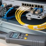
Solution: enforce connector inspection with a microscope, standardize on verified patch cords, and measure with an optical power meter and light source at commissioning and after any re-termination.
Pitfall 2: DOM or transceiver compatibility issues cause flaps or link-down events
Root cause: strict optics validation in switch firmware, mismatched DOM thresholds, or unsupported digital diagnostics behavior with certain transceiver SKUs.
Solution: use a validated optics matrix per switch model, test the exact transceiver part numbers (example third-party: FS.com SFP-10GSR-85 class) in the target switch, and lock firmware versions during the pilot.
Pitfall 3: Monitoring gaps in passive branch designs slow fault isolation
Root cause: splitter-based branching without per-branch measurement points means the alarms identify the segment, not the specific failing branch.
Solution: add disciplined test points, maintain accurate labeling maps, and consider staged measurement during incidents (for example, isolate by patch panel section before escalating). In some designs, you can place active monitoring closer to the splitter without fully converting the architecture.
Cost and ROI note for data center solutions
Cost varies widely by distance, transceiver type, and how many powered modules you deploy. As a practical range, OEM optics and active modules can cost more upfront (often several hundred dollars per transceiver/module depending on speed and reach), while passive splitters are typically lower per component but can increase field labor if labeling and cleanliness are not mature.
ROI typically comes from reduced outage duration and reduced power draw. Active approaches may increase power consumption per cabinet due to powered devices, but they can reduce mean time to repair by providing better telemetry. Passive approaches reduce power and can lower parts count, but they shift troubleshooting effort toward disciplined fiber management.
For TCO modeling, include: purchase price, spare inventory needs, power per device, expected failure rates from vendor reliability guidance, and labor hours during incident response. Use your historical ticket data to estimate how much time your team spends locating fiber faults; that number often dominates ROI more than the optics unit price.
FAQ
Which is better for data center solutions: active or passive optical?
It depends on your operational priorities. Active designs usually improve fault isolation and telemetry, while passive optical network solutions reduce powered components and can lower energy use. Many real deployments use a hybrid model: passive branching with active edge monitoring.
Do I need special transceivers to use passive splitters?
Not inherently. You still need transceivers that match your Ethernet PHY requirements and your fiber type, but passive splitters do not change the basic transceiver compatibility rules. The key is ensuring your worst-case optical budget accounts for splitter insertion loss and patching losses.
Can I mix OEM and third-party optics safely?
Often yes, but you must validate on your specific switch model and firmware. DOM support and diagnostics thresholds can differ across vendors, leading to link flaps or alarm states. Build a validated optics matrix and test during a pilot before scaling.
What optical measurements should I take during commissioning?
Measure transmit power and receive power at the far end, then record DOM values and error counters under normal traffic. For passive designs, repeat checks after any re-termination or patch panel changes. If available, verify with OTDR for fiber continuity and locate high-loss events.
How do I reduce troubleshooting time with passive branch architectures?
Invest in disciplined fiber labeling, patch panel mapping, and consistent connector standards. Add measurement points where it makes sense and use a structured incident workflow to isolate by segment quickly. If your NOC relies on automation, consider where active telemetry is worth the extra cost.
What standards should I reference during design reviews?
Reference IEEE 802.3 for Ethernet PHY behavior, and the relevant vendor datasheets for optics parameters and DOM behavior. For cabling plant practices, also align with ANSI/TIA guidance on fiber cabling and testing procedures. Use these references to justify your link budget and acceptance criteria.
Choosing the right active vs passive approach for data center solutions is less about ideology and more about measurable reach, telemetry, and operational workflow fit. If you want the next step, review your transceiver and fiber plant assumptions and standardize your validation process with fiber optic transceiver selection.
Author: I have deployed and troubleshot leaf-spine optics, VLAN-aware fabrics, and fiber cabling acceptance tests in enterprise and colocation environments. My focus is practical routing, switching, and optical design decisions that reduce downtime and rework.