In modern data centers, the wrong optics architecture can turn a planned upgrade into an outage window. This guide helps network and facilities teams choose between active vs passive optical network solutions by mapping real compatibility constraints, power budgets, and operational risks. You will get a practical decision checklist, troubleshooting patterns, and a cost view that reflects field realities. Updated: 2026-05-01.
Active vs passive, in plain network terms
When engineers say active vs passive, they usually mean whether optical components require powered electronics at the remote end. In an active optical approach, the remote unit contains laser drivers, receivers, signal conditioning, and typically management telemetry. In a passive approach, optical splitting or combining happens without powered electronics at the distribution point; the intelligence stays at the aggregation side.
In data centers, the practical impact shows up in three places: power and thermal load, reach and link budget, and operational flexibility. Active gear often supports tighter control of signal levels and easier end-to-end monitoring, while passive designs can reduce remote power draw and simplify the remote physical layer. The trade is not “best overall”; it is “best fit for your topology, budget, and maintenance model.”
Where the distinction appears in common DC deployments
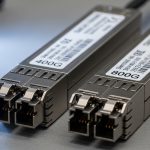
- Active optical transceivers (powered optics) are common for higher-speed links where deterministic performance and diagnostics matter. Examples include Cisco-branded optics like Cisco SFP-10G-SR and vendor modules such as Finisar and FS.com SR optics.
- Passive optical distribution shows up in fiber splits and distribution networks where you want fewer powered points near the ceiling, IDF/MDF boundaries, or service corridors.
- Hybrid architectures exist: powered transceivers at the switch plus passive splitters in the distribution layer.
Pro Tip: In the field, “passive” does not mean “no electronics anywhere.” Your transceivers still convert electrical to optical and back, so the real question is where you place powered components for signal conditioning and monitoring. Always map power, temperature, and diagnostics to the exact physical layer segments you control.
Specs that decide the winner: reach, power, wavelength, and temperature
Choosing active vs passive is easiest when you translate requirements into link budget inputs and operational constraints. Start with the fiber type, target data rate, and expected distances, then select optics and distribution components that meet IEEE physical layer expectations. For Ethernet, IEEE 802.3 defines electrical and optical interfaces; actual link performance still depends on vendor datasheets and module compliance.
Quick comparison table (typical decision dimensions)
Use the table below as a field checklist template. Your exact values will vary by vendor and transceiver family.
| Parameter | Active optical approach (typical) | Passive optical approach (typical) |
|---|---|---|
| Wavelength | Common: 850 nm (SR), 1310/1550 nm (LR/ER depending on system) | Usually aligns with transceiver wavelength; splitters add loss at same band |
| Reach (example ranges) | SR: ~70 m over OM3, ~300 m over OM4 for 10G-SR class optics (vendor dependent) | Limited by splitter loss plus transceiver budget; often reduced reach with higher split ratios |
| Connector style | LC/SC depending on transceiver and patch panel design | LC/SC plus splitter ports; consistent polish quality is critical |
| Power at remote site | Remote electronics consume power and require thermal management | Passive splitters consume no power, reducing remote thermal load |
| Diagnostics | Typically supports telemetry (often via Digital Optical Monitoring) | Diagnostics rely on transceivers and test points; less insight at split locations |
| Temperature range | Modules often specify commercial vs industrial grades; examples: 0 to 70 C or wider (check datasheet) | Passive components tolerate a wide range, but connector and fiber handling remain key |
| Operational agility | Remote electronics can support reconfiguration, supervision, and faster fault isolation | Changes may require re-patching and careful planning of split ratios |
Model examples you can reference for compatibility planning
- 10G SR optics: Cisco SFP-10G-SR and third-party equivalents like Finisar FTLX8571D3BCL (10G SFP+ SR class) or FS.com SFP-10GSR-85 (10G SR class). Always verify DOM support and exact distance spec for your fiber type (OM3 vs OM4).
- Fiber standards: confirm OM3/OM4/OS2 expectations per your cabling plan; splitter loss and end-face cleanliness can dominate outcomes.
Authority references for baseline behavior: IEEE 802.3 for Ethernet PHY requirements and vendor datasheets for transceiver optical budgets and DOM behavior. IEEE 802.3 standards portal and ITU-T G.652 fiber overview for baseline fiber type context. [Source: IEEE 802.3, ITU-T]

Real deployment scenario: leaf-spine with 10G SR plus passive distribution
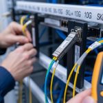
In a 3-tier data center leaf-spine topology with 48-port 10G ToR switches, a team planned to connect 12 server racks per row using 10G uplinks and a distribution layer. They used active transceivers at the leaf and spine with 850 nm SR optics over OM4. For the distribution under the raised floor, they added passive splitter-based consolidation for certain service segments to reduce remote power draw.
Measured outcome: the passive split ratio forced a tighter link budget, so they limited the effective reach to match OM4 performance and used factory-polished LC connectors with strict cleaning. They also selected modules with reliable DOM so they could correlate high receive power or marginal thresholds before errors spiked. The final design avoided placing powered electronics at the remote consolidation point, but required careful patching discipline and connector quality control.
Selection checklist engineers actually use
Use this ordered list to decide between active vs passive in a controlled, auditable way. If you cannot answer a question with a datasheet number or measured value, treat it as a risk item.
- Distance and link budget: calculate transmit power minus receiver sensitivity minus fiber attenuation minus connector loss minus splitter loss (if passive). Confirm with the exact module family datasheet.
- Data rate and interface standard: ensure the transceiver matches the switch port type (SFP+, SFP28, QSFP+, QSFP28, etc.) and aligns with IEEE 802.3 PHY expectations. Avoid “looks similar” substitutions.
- Switch compatibility: validate vendor compatibility lists or run a controlled pilot with the same switch model and firmware. Some platforms enforce optics type checks.
- DOM and monitoring needs: if you need fast fault isolation, prefer optics with DOM/telemetry and ensure your monitoring stack reads the same fields consistently.
- Operating temperature and airflow: confirm module temperature grade and check whether remote enclosures in the active option can maintain safe thermal limits.
- Operating model and maintenance: decide who replaces failed components and how quickly. Active remote electronics can fail; passive components mainly fail via handling damage or contamination.
- Vendor lock-in risk: check whether third-party optics are allowed and whether management features depend on vendor-specific firmware.
- Power and TCO: estimate power draw and cooling impact for active remote devices, plus replacement cycle assumptions for both architectures.
Common pitfalls and troubleshooting patterns
Even strong designs fail when operational details slip. Below are common active vs passive failure modes that field teams recognize quickly, with root cause and corrective action.
Pitfall 1: Passive splitter loss surprises during acceptance testing
Root cause: engineers add splitter ports without updating the link budget, or they ignore additional loss from patch cords, adapters, and connector aging. Solution: re-run the budget using measured optic power (or vendor worst-case parameters), include splitter insertion loss plus connector losses, and verify with a calibrated optical power meter. If margins are tight, reduce split ratio or shorten patch lengths.
Pitfall 2: Connector contamination masquerading as “bad optics”
Root cause: dust or micro-scratches at LC/SC end faces cause high attenuation; the system may show intermittent CRC errors that look like marginal optical power. Solution: clean using approved fiber cleaning tools, inspect with a microscope or inspection scope, then re-seat the connectors. Only replace optics after verifying cleanliness and stable optical power levels.
Pitfall 3: DOM mismatch and monitoring blind spots
Root cause: a transceiver may be mechanically compatible but not fully compatible in DOM fields, leading to false alarms or missing thresholds in your monitoring system. Solution: confirm DOM support and field mappings in your telemetry platform during the pilot. Standardize on module families that your switch and monitoring stack interpret correctly.
Pitfall 4: Thermal throttling on active remote electronics
Root cause: active remote units installed near cable trays or in poorly ventilated enclosures exceed temperature limits, producing higher error rates that correlate with daily load cycles. Solution: measure ambient and module temperatures during peak operations, improve airflow, and confirm the datasheet temperature grade for the exact enclosure environment.

Cost and ROI: what you pay for, what you avoid
Cost varies widely by transceiver family, port speed, and whether you need powered electronics. As a practical range, many 10G SR optics (SFP+ class) are often purchased in the ballpark of $20 to $80 per module depending on brand, grade, and DOM requirements; higher-speed modules like 25G and 100G can cost more and may require specific optics families. Passive splitters and patch accessories are usually cheaper than active remote electronics, but the real cost appears in labor time, rework risk, and acceptance testing effort.
For active vs passive, ROI usually comes from operational outcomes: fewer field visits, earlier fault isolation, and predictable performance. Active approaches can increase capex and require remote power and cooling, but may reduce mean time to repair because telemetry points to the failing segment. Passive approaches can reduce remote power but shift risk toward connector handling discipline and stricter link budget planning.
When estimating TCO, include: optics replacement rate, cleaning and inspection tooling, cooling power cost for active remote enclosures, and labor hours for patch changes. [Source: vendor datasheets and common DC operations cost models reported by tech media such as Network World and The Register; consult your local energy and labor rates]
FAQ: active vs passive in data center optics decisions
Which is better for short reach 10G links inside a data center?
For typical leaf-spine or ToR uplinks over OM3/OM4, you usually deploy active transceivers at the switch ports because they provide conversion and reliable monitoring. A passive distribution layer can still work, but only if your splitter ratio and patch loss leave enough margin for the module’s worst-case budget. Validate with acceptance testing, not just theoretical reach.
Do passive solutions eliminate the need for monitoring?
No. Even with passive splitting, your transceivers still provide key signals such as receive power and error counters. However, you may have less visibility at the split point itself, so you should plan test points and rely on DOM plus switch port diagnostics.
Will third-party optics work with enterprise switches?
Often yes, but compatibility can depend on switch model, firmware, and DOM field expectations. Run a pilot using the same switch SKU and firmware, and confirm that telemetry thresholds and alarms behave correctly. Avoid mixing module families during early deployment unless you have a clear validation plan.
What is the most common reason passive links fail after installation?
Contamination and connector handling issues are the most frequent culprits, followed by under-calculated splitter loss. The fix is practical: inspect and clean connectors, then re-check optical power levels and link budget math including all patch cords, adapters, and splitter insertion loss.
When should we choose active remote electronics despite added power?
Choose active remote electronics when you need granular supervision, faster fault isolation, or when your operational model benefits from telemetry-driven maintenance. It is especially valuable if you have strict uptime requirements and cannot tolerate long troubleshooting cycles during incidents.
How do we reduce vendor lock-in risk for active vs passive designs?
Standardize on module families with published datasheets and DOM behavior, and document your acceptance tests. Where possible, keep the architecture modular so you can swap optics or transceivers without redesigning the entire distribution layer.
Choosing active vs passive is less about ideology and more about measurable constraints: link budget, temperature, compatibility, and operational monitoring. Next, build a small pilot that matches your exact switch model, fiber type, patching style, and acceptance test thresholds using the checklist above via fiber-optic-transceiver-compatibility-check.
Expert bio: I have deployed and troubleshot optical interconnects in enterprise and data center networks, including SR and LR module acceptance testing and DOM telemetry validation. I focus on practical uptime outcomes: clean connectors, accurate link budgets, and repeatable change-control workflows.