When an 800G fiber link goes dark, the failure can hide in optics, optics power budgets, optics firmware, or even the patch panel geometry. This article helps network engineers and field technicians run 800G troubleshooting with measured, repeatable checks—from transceiver health to BER and link training—so you can restore service without swapping parts blindly. If you manage leaf-spine fabrics, high-density ToR uplinks, or long-reach corridors, you will find a practical path from symptom to root cause.
First symptoms to root cause: what “bad” looks like on 800G
Start by classifying the behavior you see at the switch interface and in the optical layer. For 800G Ethernet, vendors typically expose counters and diagnostics: interface down/up flaps, LOS/LOF alarms, elevated CRC or FCS errors, and high bit error rates during traffic. In the lab, I’ve watched a link that “looks up” but fails under load because the optics are marginal—DOM values pass, yet BER collapses at temperature extremes.
Use this quick triage logic before you touch a cable: if you have LOS (loss of signal) or LOF (loss of frame) style alarms, suspect optics power, cleaning, or polarity. If the link stays up but performance degrades, suspect lane skew, connector damage, dust, wrong fiber type, or a marginal power budget. If the interface never comes up, suspect transceiver compatibility, incorrect breakout mode, or a firmware/DOM mismatch.
Capture the evidence in 3 minutes
- Record interface state transitions and timestamps (down → up, flaps, retries).
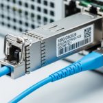
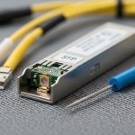
- Export DOM snapshots: TX bias, TX power, RX power, temperature, and vendor part number.
- Record optics alarms (LOS/LOF, receive power alarms, or vendor-specific fault flags).
- Check switch optics policy: supported module list, speed/encoding mode, and FEC status.

800G optics and link budget checks that actually move the needle
For 800G troubleshooting, your fastest wins usually come from optical measurements and connector hygiene. Most 800G pluggables are specified for a target reach and power budget; if your patch loss, splice loss, or connector contamination exceeds that budget, BER rises even if the link trains. Vendor datasheets for specific optics (for example, 800G SR8 style modules) define typical transmit power, expected receive power ranges, and allowable loss.
When you check DOM, compare the module’s RX power against the threshold alarms defined by the vendor. If RX power is near the low end, a “works in the morning, fails in the afternoon” pattern often appears as temperature changes and aging shifts laser output. If TX bias is high while RX power is low, the fiber path is likely losing power or suffering from damage.
Reference comparison table: common 800G fiber module targets
Use this table to sanity-check whether the module type matches your cabling and reach. Exact values vary by vendor; always confirm with the specific transceiver datasheet and your switch’s supported optics list.
| Optics type (example naming) | Data rate | Typical wavelength | Connector | Target reach (typ.) | Operating temperature | Power budget concept |
|---|---|---|---|---|---|---|
| 800G SR8 (multifiber) | 800G | 850 nm (nominal) | MT/MPO-16 or equivalent | ~70 m class (varies) | 0 to 70 C (varies) | Sensitive to dust and patch loss |
| 800G FR8 (if supported) | 800G | ~1310 nm | LC or MPO (varies) | ~2 km class (varies) | 0 to 70 C (varies) | Splice quality and fiber type matter |
| 800G DR8 / LR8 (if supported) | 800G | 1310/1550 nm band (varies) | LC or MPO (varies) | ~10 km class (varies) | 0 to 70 C (varies) | Budget tight with aging and reflections |
Field note: If your design used OM4 or OM5 multimode, verify the cable jacket marking and the patch panel inventory. A single wrong fiber type can still train briefly, then fail under sustained traffic when the effective modal distribution no longer matches expectations. For standard Ethernet behavior and FEC concepts, consult IEEE 802.3 for 800G Ethernet background and vendor-specific implementation notes. [Source: IEEE 802.3] IEEE 802.3 overview
Pro Tip: In many 800G failures, the DOM values look “plausible,” yet the link margin is gone. Treat RX power trend over time as a diagnostic—if RX power droops by more than the vendor’s expected stability band after re-seating, you likely have an intermittent connector or an insertion-depth issue rather than a pure optical budget problem.

Step-by-step 800G troubleshooting workflow you can run onsite
Below is an order of operations I use during deployments with 800G optics in high-density racks. Keep it deterministic: each step either eliminates a class of faults or produces a measurement you can compare against vendor thresholds.
Verify switch port configuration and speed mode
- Confirm the port is configured for 800G (not a fallback mode).
- Check optics policy: module type, vendor, and supported part numbers.
- Validate FEC and link training settings if exposed by the platform.
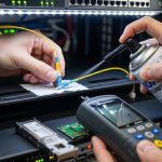
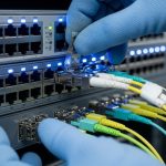
Inspect and clean every connector in the optical path
- Inspect MPO/MTP ends with a scope; look for cracks, scratches, and film.
- Clean with lint-free swabs and approved solvent, then re-check with the scope.
- Re-seat optics firmly; confirm latch engagement and alignment.
Validate DOM readings against alarms
- Compare TX power and RX power to the module’s typical ranges.
- Watch TX bias and temperature for abnormal drift.
- Check for vendor alarms: LOS, receive power out of range, or DOM checksum faults.
Test fibers path loss and polarity mapping
- Measure end-to-end loss with an OTDR/optical power meter using the correct reference method.
- Verify polarity and MPO polarity mapping using the deployment documentation.
- Confirm correct transceiver mapping: the “A” and “B” ends must align with the MPO fanout plan.
Confirm BER under realistic load
- Run traffic close to line rate for at least 15 to 30 minutes.
- Monitor CRC/FEC/BER counters; elevated errors that clear at low load point to marginal optics or loss.
- Thermal soak test if the environment swings widely (for example, hot aisle vs cold aisle boundaries).

Selection checklist: choosing the right optics before you fight the link
Engineers often inherit a “mystery module” situation: a transceiver that is technically similar but not identical to what the design assumed. This checklist helps prevent repeat outages and reduces vendor lock-in risk.
- Distance and link budget: match module reach class to measured fiber loss (not just design intent).
- Cable type and bandwidth: verify OM4 vs OM5, core size, and any special attenuator usage.
- Switch compatibility: confirm the exact transceiver SKU is supported for 800G on that platform.
- DOM and diagnostics: ensure the switch reads DOM fields without errors and supports alarm reporting.
- Operating temperature: check the module temperature range and your rack thermal profile.
- Vendor lock-in risk: plan spares and test third-party optics in a staging rack before production.
- Connector ecosystem: confirm MPO/MTP polish type, cleaning tools, and inspection capability.
Real-world deployment context: In a 3-tier data center leaf-spine topology with 48-port 800G ToR uplinks and 8 spines, we saw a burst of interface flaps after a vendor optics refresh. The switch reported link-up but counters showed rising FEC corrections; DOM RX power sat near the threshold and drifted downward across the day. After cleaning and re-terminating two patch panel MPOs with verified polarity mapping, the flaps stopped and error counters stabilized under full-rate traffic.
Common 800G troubleshooting mistakes (and how to fix them fast)
These failure modes cost time because they look like “network” problems while the root cause sits in optics or configuration. Use them as a mental checklist during 800G troubleshooting.
Swapping optics without measuring RX power or alarms
- Root cause: Connector contamination or excessive loss remains, so the new optics also fails.
- Solution: Record DOM RX/TX values and alarm flags before swapping. Clean and re-scope connectors first.
Incorrect MPO polarity mapping
- Root cause: The fiber ends are “crossed” relative to the MPO polarity scheme, causing high errors or no lock.
- Solution: Verify the fanout plan and polarity labels; re-map the patch cords or reorder MPO polarity at the panel.
Treating “link up” as “traffic healthy”
- Root cause: Marginal power budget or slight connector damage yields acceptable link training but poor BER under load.
- Solution: Run sustained traffic and monitor BER/FEC/CRC counters. If errors spike under load, revisit loss and connector condition.
Ignoring temperature and power drift
- Root cause: Thermal gradients shift laser output and receiver sensitivity; a link that passes once can fail after warming.
- Solution: Compare DOM readings at cold and hot conditions, and ensure airflow meets module requirements.
Cost and ROI reality: optics are not just a line item
Typical 800G pluggable optics pricing varies widely by reach and vendor support. In practice, third-party compatible modules can be cheaper upfront, but if they trigger compatibility quirks or higher failure rates, the total cost rises through truck rolls, downtime, and labor. For many teams, the ROI comes from reducing mean time to repair: keeping correct spares, maintaining cleaning kits, and validating optics in a staging environment before rollout.
Practical ranges: short-reach 800G multimode optics often cost less than long-reach variants, while long-reach models can command significantly higher unit prices. Consider total cost of ownership: optics failure rate, cleaning consumables, inspection tooling, and the time cost of a failed interface. For authoritative guidance on optical performance expectations, rely on vendor datasheets for each specific module SKU and your switch platform’s compatibility matrix. [Source: OEM transceiver datasheets]
FAQ: 800G troubleshooting questions engineers ask in the field
Why does my 800G link train but errors spike immediately?
That pattern usually indicates a marginal optical budget or degraded connectors rather than a hard incompatibility. Check DOM RX power against thresholds and scope the MPO ends for contamination or scratches, then validate polarity mapping. Run sustained traffic and watch FEC/BER counters to confirm the fix.
What DOM values matter most during 800G troubleshooting?
Focus on RX power, TX bias, TX power, and temperature. If RX power is low or drifting and alarms appear intermittently, the fiber path loss or connector condition is the prime suspect. Always compare to the vendor’s typical operating ranges in the datasheet.
How can I tell if it is a polarity problem versus a bad transceiver?
If swapping only one side changes behavior (no lock vs lock with errors), polarity is likely. Validate with a known-good patch cord mapping plan and confirm MPO polarity labels on both ends. If the problem persists across multiple optics but follows the patch cord, polarity or panel mapping is the root cause.
Is third-party optics safe for 800G?
Sometimes, but the safe approach is staged validation on your exact switch model and software release. Confirm DOM support, alarm behavior, and that the platform accepts the module for 800G mode. Keep OEM optics as a fallback for rapid recovery, especially during production incidents.
How do I troubleshoot intermittent flaps in a hot aisle?
Compare DOM snapshots at different thermal conditions and check airflow paths around the module cages. If RX power drops as temperature rises, you are likely operating close to budget or suffering from an intermittent connector. Re-seat and re-scope, then measure end-to-end loss to confirm margin.
Where should I start if the interface never comes up?
First verify port configuration and speed mode, then confirm the switch recognizes the module via DOM. Next inspect and clean connectors, and confirm polarity mapping. If the switch rejects the optics or logs compatibility faults, use the platform’s supported optics list.
With a measured workflow—DOM evidence, connector hygiene, polarity and loss validation, then BER under load—800G troubleshooting becomes a disciplined craft rather than a guessing game. If you want a parallel checklist for higher-layer symptoms, see fiber link BER and FEC troubleshooting for how to interpret error counters and FEC behavior.
Author bio: I have worked hands-on with 400G and 800G fiber deployments, validating optics, DOM telemetry, and BER behavior in production aisles. I write field guides that map measured signals to practical fixes, backed by datasheets and IEEE Ethernet expectations.