When your leaf-spine fabric starts feeling every microsecond of latency and every watt of power, 800G adoption becomes less a roadmap item and more an operational necessity. This article helps network and infrastructure leaders plan 800G rollouts with hands-on optics choices, governance controls, and measurable ROI. You will leave with a step-by-step implementation path, including how to avoid the failure modes that field teams actually see.
Prerequisites for 800G adoption readiness
Before you buy transceivers, align architecture, cabling realities, and vendor support boundaries. In practice, most delays come from mismatched optics types, insufficient optical budget, or switch firmware that does not expose the expected Digital Optical Monitoring features.
Establish a baseline measurement plan
Expected outcome: a reference sheet that proves link budgets, thermal margins, and operational processes are ready for 800G adoption. Start by collecting current utilization and error telemetry from your switches. Capture interface counters, optical DOM readings (if available), and fan or PSU behavior under peak load.
Confirm IEEE and cabling assumptions
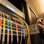
Expected outcome: documented compliance targets tied to IEEE optics expectations. For 800G Ethernet, teams typically map to IEEE 802.3 specifications for 800G PHY behavior and optics classes, then translate that into your fiber plant constraints. Validate whether your current MPO/MTP infrastructure supports the required polarity and cleaning discipline, and whether you have enough spare fibers for parallel builds.
Reference: IEEE 802.3 and vendor datasheets for specific reach and modulation details. For structured cabling constraints, cross-check ANSI/TIA guidance via ANSI/TIA webstore.
Define governance for optics and firmware
Expected outcome: a controlled change process that prevents “works on my rack” drift. Create an allowlist for transceiver part numbers per switch model, and require firmware baselines before any optics are introduced. Require DOM verification during install, and define rollback triggers (for example, a sustained increase in receive power out of spec for a defined window).
Pro Tip: In field deployments, the fastest way to predict 800G adoption pain is to test DOM telemetry behavior under real traffic. Some third-party optics report temperature and bias current correctly, but omit vendor-specific diagnostic fields that your switch expects for alarms. If your monitoring scripts treat missing fields as “unknown,” you can miss early optical degradation.

selection: choose 800G optics by reach, connector, and switch compatibility
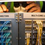
800G adoption succeeds when the optics match both the physics of your fiber plant and the engineering intent of your switch vendors. The selection must consider wavelength plan, reach class, connector type, and whether the transceiver supports the switch’s required interface mode.
Map your reach requirement to fiber plant reality
Expected outcome: a reach matrix that links rack-to-rack and pod-to-pod distances to optics reach classes. Measure actual distances (not cable labels), including patch panel lengths. Then account for insertion loss from connectors, splices, and patch cords. For multi-fiber MPO links, remember that polarity and endface cleanliness can dominate budget outcomes.
Compare common 800G optics classes and example part numbers
Expected outcome: a short list of optics that align to your distance and operational constraints. While exact offerings vary by vendor, teams often evaluate short-reach and medium-reach pluggables with specific wavelength and reach targets.
| Optics example | Data rate / lane pattern | Typical reach class | Wavelength / fiber type | Connector / interface | DOM / monitoring | Operating temperature (typ.) |
|---|---|---|---|---|---|---|
| Cisco 800G optics (vendor-specific modules for QSFP-DD/OSFP platforms) | 800G aggregate (vendor-defined) | Typically short to medium for data center links | Multi-lane optical channels over OM4/OM5 or SMF depending on model | QSFP-DD or OSFP class (platform-dependent) | DOM supported (model-dependent) | Varies by module family; validate datasheet |
| FS.com 800G QSFP-DD optical examples (check exact SKU per reach) | 800G aggregate | Short/medium options | OM4/OM5 or SMF depending on SKU | QSFP-DD | DOM typically supported; verify field mapping | Varies; validate datasheet |
| Finisar / Finisar-origin 800G pluggables (availability varies) | 800G aggregate | Short to medium reach depending on SKU | Multi-channel optical signaling | QSFP-DD or platform-specific form factor | DOM supported (datasheet dependent) | Varies; validate datasheet |
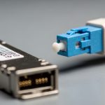
Because 800G adoption is highly platform-specific, do not treat “800G” as a single interchangeable commodity. Validate the exact form factor (for example, QSFP-DD vs OSFP), the lane configuration, and the switch firmware compatibility matrix provided in vendor release notes.
For concrete reference, always read the optics datasheet for the exact SKU you plan to deploy, and cross-check switch vendor compatibility documentation. Use Cisco support pages for optics compatibility lists, and vendor datasheets for DOM and temperature ranges.
Lock polarity, cleaning, and insertion loss controls
Expected outcome: fewer link bring-up failures and lower long-term error rates. Establish a cleaning SOP for MPO/MTP endfaces (lint-free wipes plus approved cleaning tools), and enforce polarity labeling that matches the transceiver and patch panel design. In 800G adoption, the number of fibers per link increases the chance that one endface defect becomes a systemic outage.

Architect the rollout: phased 800G adoption with measurable governance
Rollout planning turns 800G adoption from a procurement event into a controlled engineering program. A phased approach lets you validate optics behavior, monitoring accuracy, and operational runbooks before scaling.
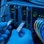
Run a pilot in a controlled failure domain
Expected outcome: a pilot that proves optics and telemetry under production-like load. Choose one pod or one leaf-pair set, and isolate it in a maintenance window. Load traffic patterns that represent your real mix: east-west flows, microbursts, and sustained throughput. Monitor link error counters, DOM thresholds, and switch CPU impact from telemetry polling.
Define acceptance tests and rollback criteria
Expected outcome: explicit go/no-go gates that prevent “soft failures” from spreading. Acceptance tests should include: link up/down stability over a sustained period, DOM readings within datasheet ranges, no interface flaps, and stable forward error correction indicators (if exposed by your platform). Roll back if you see persistent receive power drift, alarm storms, or repeated resync events.
Integrate monitoring and governance into daily operations
Expected outcome: ongoing compliance that reduces mean time to repair. Create alert rules that trigger on threshold crossings such as temperature rise, bias current anomalies, or receive power outliers. Ensure that your network management system can ingest DOM fields reliably for the optics you deploy. If you use third-party optics, verify that monitoring templates do not assume vendor-specific telemetry keys.
- Distance and reach: measured cable lengths plus insertion loss budget, mapped to the optics reach class.
- Switch compatibility: exact form factor and firmware release notes; validate allowlists.
- DOM support: confirmed alarm and telemetry field mapping in your monitoring tooling.
- Operating temperature: confirm module and chassis thermal envelopes under sustained load.
- Connector and polarity: MPO/MTP polarity plan, cleaning SOP, and spare patch strategy.
- Vendor lock-in risk: evaluate OEM vs third-party availability, return policies, and support boundaries.
- Operational readiness: runbooks for link bring-up, DOM interpretation, and safe rollback.

Common pitfalls and troubleshooting during 800G adoption
Even well-planned 800G adoption can stumble. These are the failure modes that repeatedly appear in field bring-ups, along with root causes and fixes.
Top failure point 1: Link flaps immediately after optics insertion
Root cause: polarity mismatch or endface contamination on MPO/MTP connectors. High lane counts amplify the impact of one bad interface.
Solution: clean both ends, verify polarity against the transceiver and patch panel design, and re-seat the transceiver firmly. Perform a controlled swap with known-good optics and a known-good patch cord set.
Top failure point 2: DOM alarms show but interface counters look normal
Root cause: monitoring template mismatch or missing telemetry fields from third-party optics. Your system may interpret “unknown” as a threshold breach.
Solution: validate the DOM field mapping for the exact SKU in a staging environment. Update alert rules to use vendor-agnostic thresholds where possible, and confirm that the monitoring collector parses fields correctly.
Top failure point 3: Performance degrades after a few days under peak load
Root cause: thermal stress or marginal optical budget that only fails under sustained temperature and power. Bias current and receive power drift can push links out of safe operating margins.
Solution: check airflow paths and confirm the chassis fan profile under peak conditions. Re-measure optical budget and inspect patch panels for damaged connectors. If needed, move to a shorter reach optics class or reduce insertion loss with optimized patch cords.
Cost and ROI note for 800G adoption
Cost is not just the optics price; it is the operational friction and downtime risk. In many data centers, OEM optics carry a premium but often come with clearer compatibility matrices and faster support escalations, which can reduce mean time to resolution during rollouts. Third-party optics can reduce upfront spend, but you must factor compatibility testing time, return logistics, and monitoring integration work.
As a practical range, many teams see optics pricing fluctuate widely by reach and form factor, often spanning from hundreds to over a thousand USD per transceiver depending on SKU and supply conditions. TCO improves when you standardize on a small optics portfolio, reduce truck rolls by strengthening acceptance tests, and prevent repeat failures through cleaning and polarity governance. For ROI, quantify avoided downtime hours and reduced operational overhead from reliable telemetry and stable link bring-up.
FAQ: 800G adoption decisions engineers ask before buying
What does “800G adoption” actually require at the hardware level?
It requires switch support for the specific 800G PHY and the correct pluggable form factor, plus a fiber plant that meets reach and polarity requirements. You also need monitoring readiness so DOM telemetry drives actionable alerts rather than noise.
Can we mix OEM and third-party optics during 800G adoption?
You can, but only within a controlled compatibility boundary defined by your switch vendor and your monitoring system. Perform a pilot and validate DOM field mapping, alarm behavior, and link stability before any broad mix-and-match strategy.
How do I choose between short-reach and medium-reach optics?
Start with measured distances and insertion loss, then add margin for aging, connector variability, and patch cord replacements. If your budget is tight, choose the optics class with the safer margin rather than the cheapest that barely meets the spec.
What is the most common cause of 800G link bring-up failure?
MPO/MTP polarity mistakes and endface contamination are frequent culprits. Clean and polarity-verify every link as a governed step, not a best-effort task.
How should we handle firmware and optics lifecycle governance?
Pin your rollout to a tested switch firmware baseline and only update after optics compatibility is revalidated. Maintain an allowlist of transceiver SKUs and require change tickets for any deviation, especially during 800G adoption waves.
Is there a measurable operational benefit beyond throughput?
Yes. When telemetry and alarms are correct, teams reduce troubleshooting time and prevent silent optical degradation. That operational reliability often yields the ROI that justifies the transition.
800G adoption is a choreography of optics physics, switch compatibility, and governance discipline, not a single purchase order. Next, align your rollout to a repeatable process by reviewing related topic on fiber plant management for high-speed Ethernet.
Author bio: I have designed and deployed high-density Ethernet fabrics, validating optics compatibility, DOM telemetry, and thermal behavior during staged rollouts. I write from field experience, translating vendor datasheets and IEEE expectations into operational runbooks that survive real maintenance windows.