Buying a 400GbE fiber module sounds easy until you plug it in and watch link training fail like a sitcom punchline. This article helps network engineers and data center field teams choose and deploy 400G QSFP-DD800 transceivers built on 8-lane technology, with real compatibility and troubleshooting details. You will also get selection criteria, a spec comparison table, and pragmatic failure-mode fixes you can apply on site.
Why 8-lane QSFP-DD800 optics change your 400GbE fiber module checklist
Traditional 400G optics often translate to specific lane counts and electrical serialization patterns inside the transceiver. With QSFP-DD800, you typically deal with an 8-lane optical interface, meaning each lane carries a fraction of the total payload rate while the module manages FEC, CD compensation, and clock/data recovery. In practice, that impacts what you must verify: switch port optics support, expected lane mapping, FEC mode alignment, and reach assumptions based on fiber type and link budget.
From an operational perspective, the “gotcha” is that a module can be electrically compatible but still fail due to mismatched settings, vendor-specific DOM behavior, or incorrect cabling polarity assumptions. For 400G deployments, those issues show up as intermittent link flaps, high BER during margin testing, or a cleanly inserted module that never reaches “link up.” IEEE 802.3 defines Ethernet PHY behaviors at these speeds, while module vendors specify the exact optical performance and management expectations in their datasheets. For standards context, see IEEE 802.3 and vendor DOM/optics documentation.
Pro Tip: When swapping 400GbE optics, always compare the switch’s expected FEC mode and lane mapping with the module’s advertised capabilities via DOM. Many “mystery failures” are not bad optics at all, but an FEC or configuration mismatch that only shows up under cold-start or temperature drift.
Key specifications to compare before you order (wavelength, reach, power)
Different vendors brand similar-looking modules with different optical power budgets, connector types, and temperature grades. A 400GbE fiber module is only as reliable as its worst-case link budget at your target temperature and aging assumptions. The table below compares common QSFP-DD800-style options you are likely to evaluate for short-reach and extended-reach campus or data center links.
| Spec | Common QSFP-DD800 SR8 (Multimode) | Common QSFP-DD800 LR8 (Single-mode) | Common QSFP-DD800 ER8 (Single-mode, extended) |
|---|---|---|---|
| Data rate | 400G (8-lane) | 400G (8-lane) | 400G (8-lane) |
| Wavelength | 850 nm class | 1310 nm class | 1550 nm class |
| Typical reach* | ~100 m to ~150 m (OM4/OM5 dependent) | ~2 km | ~10 km (varies by spec sheet) |
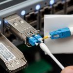
| Connector | LC duplex (often MPO/MTP variants exist) | LC duplex or LC interface per module | LC duplex |
| Optical power (Tx) | Vendor range; verify dBm and min launch power | Vendor range; verify dBm and min launch power | Vendor range; verify dBm and min launch power |
| Receiver sensitivity | Vendor range; verify dBm for BER target | Vendor range; verify dBm for BER target | Vendor range; verify dBm for BER target |
| DOM | Supported (verify compliance and fields) | Supported (verify compliance and fields) | Supported (verify compliance and fields) |
| Operating temperature | Commercial/industrial grades exist; verify range | Commercial/industrial grades exist; verify range | Commercial/industrial grades exist; verify range |
*Reach depends on fiber grade (OM4 vs OM5), patch panel losses, and link budget assumptions. Always validate against the module vendor datasheet and your site loss measurements.
When comparing products, look beyond marketing reach. Confirm the fiber type (OM4 vs OM5), the connector and polarity expectations (especially for MPO/MTP), and the module’s Tx/Rx power and receiver sensitivity. For concrete examples of commonly referenced parts in the ecosystem, you may see QSFP-DD 400G optics from OEM and third-party vendors such as Cisco-branded optics and widely sold variants like Finisar/II-VI parts (for example: Finisar) or FS.com catalog listings (for example: FS.com). Always match the exact part number to your switch model.

Real-world deployment: 3-tier leaf-spine with 48-port 400G optics
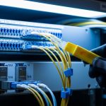
In a 3-tier data center leaf-spine topology with 48-port 10G/25G leaf switches upgraded to support 400G uplinks, teams often deploy 400G cabling in a staged rollout to avoid a big-bang cutover. Picture a cluster: 8 spine switches each with 16 active 400G uplink ports, and 24 leaf switches each needing 2 x 400G uplinks. That is 384 transceiver instances to source, label, and validate.
Field teams typically measure fiber loss using an OTDR or calibrated power meter before install, then verify end-to-end attenuation and polarity at the patch panel. During activation, the switch checks optics via DOM over I2C, applies its expected FEC setting, and attempts lane training. If a module is rated for OM4 but you accidentally used an OM3 patch path, you may see “link down” plus rising error counters. In the first week of rollout, the most common root cause is not the module itself, but patch panel loss creep: dirty connectors, high insertion loss, or mismatched polarity on MPO trunks.
Selection criteria: the ordered checklist engineers actually use
Use this ordered list to reduce surprises and keep your spare inventory sane.
- Distance and fiber grade: pick SR8 vs LR8 vs ER8 based on measured loss, not just nominal reach. Confirm OM4 vs OM5 and patch panel attenuation.
- Switch and port compatibility: verify your switch model supports QSFP-DD800 optics at 400G and the expected FEC mode. Check vendor compatibility lists and release notes.
- DOM and management expectations: ensure the module supports the required DOM parameters and that your monitoring stack reads them correctly (temperature, bias, power, alarms).
- Operating temperature grade: align commercial vs industrial transceiver requirements to your rack airflow and ambient conditions. Hot aisles are not theoretical.
- Vendor lock-in risk: if you buy OEM-branded optics, estimate replacement availability and pricing. Third-party can reduce cost, but confirm compatibility and support terms.
- Connector and polarity constraints: confirm LC vs MPO/MTP, and verify polarity conventions for your patching standard.
- Link budget margin: leave headroom for dust, aging, and occasional re-termination. If your measured link budget is tight, plan preemptive cleaning and maintenance.
To ground this in standards and vendor expectations, review IEEE 802.3 for Ethernet PHY framing and vendor datasheets for optical/electrical specs. Also consult relevant cabling guidance from ANSI/TIA for fiber practices and test methodology; see ANSI/TIA for the broader standards ecosystem.

Common pitfalls and troubleshooting tips for 400GbE fiber module installs
Below are failure modes you can expect in the field, along with root causes and what to do next. Spoiler: the fastest fix is usually the one you do before calling the vendor.
Link never comes up after insertion
Root cause: switch expects a specific FEC or lane training behavior that the module does not match, or the port is in a mode not supported by that optic. Sometimes it is also a mismatched connector type (LC vs MPO) or wrong patch polarity.
Solution: verify port configuration (speed, FEC mode if adjustable), confirm DOM readout shows “present” and no high-alarm thresholds, and cross-check cabling polarity. If the switch supports it, compare successful ports’ DOM values (Tx power, Rx power, temperature) to the failing one.
Flapping link under load, stable at idle
Root cause: marginal optical budget, dirty connectors, or patch panel insertion loss that only hurts at higher error tolerance margins. In SR links, a single high-loss patch can become the “weak link” in the chain.
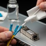
Solution: clean all optical interfaces with proper fiber cleaning tools, re-seat connectors, and re-measure link loss. Use BER/error counters and module alarms from DOM; if you see rising error rates with temperature, revisit airflow and consider lower-watt or better-rated modules.
Works in the lab, fails in the rack
Root cause: temperature or power supply behavior in the installed environment differs from bench conditions. Some modules are rated for commercial ranges but are deployed in hot aisles without airflow discipline.
Solution: log ambient temperature and module temperature via DOM during operation. Ensure rack airflow and cable routing do not block vents. If needed, switch to an industrial-grade module variant with an appropriate temperature range and confirm it is supported by the switch vendor.
High error counters after a “successful” upgrade
Root cause: incorrect expectation of OM4 vs OM5, patch cords with wrong specifications, or aging connectors causing increased attenuation. Another culprit is inconsistent polarity on MPO trunks.
Solution: standardize patch cord types, label trunks, and enforce polarity verification during change windows. Confirm fiber type using documentation and test results rather than relying on memory and hope.
Cost and ROI: what 400GbE fiber module spending looks like in year one
Pricing varies heavily by reach and vendor, but in many markets you will see QSFP-DD800 400G optics in the rough range of $250 to $900 per module depending on OEM vs third-party, distance (SR vs LR vs ER), and temperature grade. OEM optics often carry higher unit cost but may reduce integration friction due to better switch validation and support agreements. Third-party optics can cut capex, but you must budget time for validation testing and maintain a compatibility matrix.
TCO is where the real party happens: include labor hours for testing, potential downtime during swaps, cleaning and re-termination costs, and replacement failure rates. A practical approach is to buy a small pilot batch, validate optics with your exact switch model and patch plant, then scale. If you can avoid even a handful of truck rolls, the ROI becomes less “spreadsheet fantasy” and more “my pager stayed quiet.”
FAQ
What does “8-lane” mean for a 400GbE fiber module?
It means the 400G payload is distributed across eight parallel lanes inside the optical/electrical interface. Each lane runs at a lower per-lane signaling rate than a single-lane design, which affects how the module and switch perform lane training and error correction. Always confirm the switch port supports that lane architecture for QSFP-DD800.
Can I mix OEM and third-party 400GbE fiber module optics in the same switch?
Sometimes yes, but it is not guaranteed. Compatibility depends on switch firmware, supported DOM fields, FEC behavior, and whether the vendor validated that specific optic type. In the same chassis, mixing can work, but you should validate with a pilot and monitor DOM and error counters for at least a few temperature cycles.
How do I choose between SR8, LR8, and ER8?
Base the choice on measured distance and link loss, not just the headline reach number. SR8 is usually for shorter distances over OM4/OM5 multimode fiber, while LR8 and ER8 are for longer runs on single-mode fiber. If your patch panel is lossy or connectors are aging, pick the option with margin.
What DOM fields should I monitor during deployment?
At minimum, monitor module temperature, received optical power, transmitted optical power (if available), and any alarm/warning flags. During acceptance testing, compare DOM values from a known-good port to the new module so you can detect weak optical budget behavior early. If your monitoring system supports it, log these values over time, not just at insertion.
Why do links fail only after a few hours?
Common causes include thermal drift, airflow differences, or connectors that heat up and increase insertion loss. Another cause is marginal optical power that only crosses thresholds under load. Use DOM temperature and error counters to correlate failures with operating conditions.
Where can I verify compatibility for QSFP-DD800 optics?
Check your switch vendor’s optics compatibility list and firmware notes, then validate with a pilot batch in your specific cabling environment. Standards like IEEE 802.3 help define Ethernet behavior, but compatibility is ultimately enforced by switch PHY settings and how the vendor expects the module to present DOM data. For general standards context, see IEEE 802.3.
If you want fewer failed link bring-ups, treat a 400GbE fiber module purchase like a mini engineering project: verify reach with measured loss, confirm switch compatibility, and test optics under real thermal conditions. Next, explore 400G QSFP-DD800 vs QSFP112 design considerations|400G QSFP-DD800 vs QSFP112 design considerations to understand how interface choices ripple into cabling and failure rates.
Author bio: I design and validate high-density optical interfaces in real data centers, where “it should work” is not a strategy. I’ve deployed QSFP-DD optics across leaf-spine fabrics and learned to respect link budgets, DOM telemetry, and dirty connectors.