Multi-gig campus upgrades often fail where budgets are tight and assumptions are loose: the cables are ready, the switches are new, and yet the uplinks refuse to train reliably. This article helps campus and network engineers choose a 5GBASE-T SFP that matches real switch behavior, power limits, and environmental constraints. You will get field-tested selection criteria, a troubleshooting checklist, and a deployment scenario drawn from typical leaf-spine access designs.
Why a 5GBASE-T SFP is the campus upgrade hinge
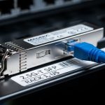
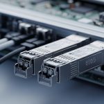
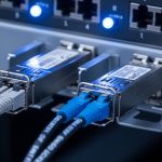
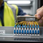
In many campuses, the bottleneck is not the WAN edge; it is the access layer where office densification, Wi-Fi 6E/7 AP growth, and video-heavy endpoints push beyond 1G. 5GBASE-T over twisted pair can deliver multi-gig throughput without pulling new fiber, but the ecosystem still demands careful optics-to-switch matching. A 5GBASE-T SFP module is typically a pluggable transceiver that presents an electrical interface profile to the switch, while the switch firmware handles training, link negotiation, and FEC where applicable.
Engineers choose it for three reasons: reach over copper that often aligns with existing structured cabling, cost avoidance versus wholesale fiber runs, and operational speed during phased cutovers. The key caveat is that not every switch that advertises 5GBASE-T on its ports will accept every third-party transceiver, and some designs require specific DOM or supported EEPROM layouts to pass diagnostics. For standards context, Ethernet link behavior is governed by IEEE 802.3 specifications for 5GBASE-T, while optical pluggables are standardized by SFP physical form factors and management expectations often described in vendor documentation and multi-source agreement style EEPROM maps. IEEE 802.3 Working Group
Pro Tip: Before buying, verify that your switch supports the exact pluggable type and revision for 5GBASE-T copper modules, not just the media speed. In the field, many “works on my bench” failures trace back to a strict vendor compatibility list or a DOM/EEPROM parsing difference that prevents link bring-up even when the PHY would otherwise negotiate correctly.

What to measure: copper reach, power, temperature, and management
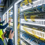
Choosing a 5GBASE-T SFP is less about marketing reach numbers and more about measurable constraints: cable category, link distance, power draw, and thermal headroom in the switch. Most campus failures happen during marginal conditions: long runs on older cabling, poor patch panel terminations, or airflow reduced by door closures and ceiling obstructions. A realistic plan starts with verifying cable category (often Cat 5e or Cat 6), end-to-end attenuation and NEXT/FEXT pass rates, and switch ambient temperature at the intake vents.
On the module side, check the transceiver’s electrical characteristics and the switch’s power budget per cage or per port group. Many pluggables include digital diagnostics (DOM) registers—temperature, supply voltage, TX/RX bias when applicable, and vendor identifiers. Even for copper, DOM support can matter for monitoring and for acceptance tests. Also confirm the operating temperature range: a module that is specified for 0 to 70 C might survive in an office closet, but not in a heat-soaked MDF with restricted airflow.
| Specification | 5GBASE-T SFP (Typical Copper Pluggable) | What to Validate in Your Switch |
|---|---|---|
| Data rate | 5.0 Gb/s (single link) | Port speed support and auto-negotiation behavior |
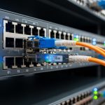
| Media | Twisted pair (RJ-45 cabling via structured cabling) | Whether your switch uses a pluggable-to-copper mapping or fixed PHY |
| Wavelength | N/A (electrical copper) | Not applicable, but verify module type acceptance |
| Connector | SFP physical form factor (module edge connector) | Correct SFP cage and mechanical fit |
| Reach (practical) | Depends on cable category and installation quality | Run certification results, not only “spec sheet” distance |
| Power consumption | Varies by vendor; check per-module draw | Switch PSU budget and per-port power limits |
| Temperature range | Often 0 to 70 C or wider | Measured ambient at the cage intake |
| DOM / diagnostics | Often includes temperature and voltage | DOM parsing support and monitoring integration |
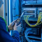
If you are comparing options, lean on vendor datasheets and switch compatibility matrices. For example, optical modules have explicit wavelength and reach specs; copper pluggables have fewer optical parameters but still publish electrical and thermal limits. For third-party evaluation, sample-testing is decisive because EEPROM layout and switch firmware parsing can differ. When you do evaluate, instrument the run: capture link state transitions, autonegotiation time, and any CRC or FCS error counters at both ends.

Real-world campus scenario: phased Wi-Fi 7 and 10G uplinks
Consider a 3-tier campus design in a mid-size enterprise: 48-port access switches at each building, aggregated into two distribution switches per building, then uplinked to a central core. The network team plans a phased upgrade for Wi-Fi 7 APs that require low-latency backhaul and multi-gig throughput, while keeping existing structured cabling. In phase one, they target 5GBASE-T uplinks from access switches to distribution for 24 AP ports and a few IP cameras, while maintaining 10G fiber for trunking where already deployed.
They start with two pilot buildings: Building A has Cat 6 certified runs averaging 38 m, Building B has mixed Cat 5e with an average of 55 m. The team installs 5GBASE-T SFP modules only after validating switch support for the exact module family and confirming that the distribution switch’s port groups do not exceed the per-slot power limit. During the cutover, they monitor link training time and CRC error counters for 48 hours, then expand the rollout only to cabinets that show stable error-free operation at peak office loads.
The operational detail that matters most is not raw throughput; it is stability under real interference. When patch panels are re-terminated or when cable management is disturbed, return loss and impedance mismatches can trigger intermittent renegotiation. The team mitigates this by running cable certification reports before and after any physical changes, then correlating those results with switch logs that capture autonegotiation outcomes.
Selection criteria checklist engineers actually use
To choose the right 5GBASE-T SFP, engineers typically walk through an ordered set of questions. This prevents expensive rework and reduces the chance of a “module accepted but link never comes up” event.
- Distance and cable quality: use certified end-to-end results (attenuation, NEXT, return loss), not only the module’s nominal reach.
- Switch compatibility: confirm your switch model and firmware version accept the module type; check the vendor compatibility list and DOM requirements.
- Auto-negotiation and speed fallback: test whether the port stays at 5G or falls back to 2.5G/1G under marginal conditions.
- DOM support: ensure temperature/voltage diagnostics are readable and usable for your monitoring system, and that alarms do not spam.
- Operating temperature: measure ambient at the cage intake; confirm the module’s operating range matches your worst-case HVAC scenario.
- Power and thermal budget: verify per-port and per-module power draw does not exceed backplane or PSU constraints during high utilization.
- Vendor lock-in risk: weigh OEM pricing versus third-party availability; plan spares by vendor and revision to simplify replacements.
- Lifecycle and RMA path: confirm return policies, warranty length, and whether the vendor can validate your specific switch firmware.
If you must compare third-party modules, request test data or run your own burn-in plan. A common practical approach is to deploy a small batch in a representative cabinet, then run traffic at peak utilization while monitoring error counters and link state changes for at least a week.

Common pitfalls and troubleshooting paths
Even experienced teams stumble. Below are frequent failure modes with root causes and solutions specific to 5GBASE-T SFP deployments in campus environments.
Link never comes up or flaps during autonegotiation
Root cause: switch compatibility mismatch or DOM/EEPROM parsing differences that cause the port to reject the module, even if the PHY could negotiate. Another common cause is a firmware requirement for a particular module family revision.
Solution: confirm module part number against the switch’s official compatibility list; update switch firmware if the vendor documents support for that module family. Then swap with a known-good OEM module to isolate whether the issue is module acceptance or cable quality.
Stable link at first, then periodic CRC or FCS errors
Root cause: marginal cabling characteristics: poor terminations, damaged pairs, or patch panel rework that increases return loss and reduces signal integrity. In multi-building campuses, this often correlates with runs that were “installed long ago” and later modified.
Solution: pull a cable certification report and compare it to the thresholds required for 5GBASE-T operation on your cabling standard. Reseat patch cords, inspect keystone jacks for bent pins or mis-terminated pairs, and re-run link-level error counters during a traffic replay test.
Unexpected power draw and thermal throttling alarms
Root cause: the switch’s airflow path is obstructed or the module operates near the upper end of its temperature range. Some cabinets experience hot spots when doors are closed or when airflow is redirected to other racks.
Solution: measure actual ambient temperature at the cage intake using a calibrated probe. If needed, adjust airflow, clear obstructions, and validate the module’s operating temperature range against your measured maximum. Also confirm you did not over-concentrate modules in a thermally constrained slot group.
Monitoring shows “module present” but metrics are missing or misleading
Root cause: DOM support differences between OEM and third-party modules, including different register maps or reduced telemetry sets.
Solution: align monitoring expectations with what the module reports. In practice, map DOM alarms to vendor documentation and validate that your NMS reads the same fields the switch exposes.
Cost and ROI: where savings are real, and where they vanish
In many campus programs, 5GBASE-T SFP modules are chosen to avoid fiber trenching or to defer fiber until a later lifecycle. Price varies widely by OEM versus third-party suppliers, warranty terms, and availability during procurement windows. As a realistic planning range, OEM copper pluggables may land in the ballpark of $80 to $160 per module, while third-party equivalents might be $40 to $90, depending on compatibility guarantees and volume discounts.
TCO is driven by more than purchase price. Consider failure rate and replacement logistics: a module that is slightly cheaper but triggers frequent flaps can cost more in engineer hours, downtime risk, and truck rolls. Power savings can be modest: if your alternative is running higher-speed optics or adding active copper extenders, you may save watts per port, but the dominant ROI often comes from avoided cabling work and faster deployment cycles.
Mitigation strategy: standardize on one or two approved module families, keep a spares pool sized to your mean time to repair targets, and record module part numbers alongside switch firmware versions in your change management system.
FAQ for engineers buying 5GBASE-T SFP modules
Which switch models support a 5GBASE-T SFP reliably?
Support depends on the switch hardware platform and firmware version, not just the advertised port speed. Check your vendor’s compatibility list for the exact 5GBASE-T SFP part number and confirm DOM parsing compatibility.
Can I mix OEM and third-party 5GBASE-T SFP modules in the same chassis?
It can be possible, but it increases troubleshooting complexity because DOM and acceptance behavior may differ. If you mix vendors, test in a pilot cabinet first and ensure your monitoring system handles differences in telemetry availability.
How do I validate cable readiness before installation?
Use a certified link tester and capture results for attenuation, NEXT, return loss, and pair integrity. Then correlate those results with a staged deployment where you monitor CRC/FCS error counters for at least several days under realistic traffic.
What happens if the link negotiates down to 2.5G or 1G?
That behavior usually indicates marginal signal quality or policy constraints in the switch or module. Re-check cabling certification, patch panel terminations, and any intermediate patch cords; also confirm that your switch allows 5GBASE-T to remain preferred rather than fallback under certain error thresholds.
Do I need DOM for operations?
DOM is not always required for basic link functionality, but it is valuable for fleet monitoring and early failure detection. If your NMS expects specific DOM registers, verify that the module supports the telemetry your tooling needs.
What is the safest rollout strategy for a multi-building upgrade?
Use a pilot phase with representative cabling lengths and cabinet airflow conditions, then expand with standardized module part numbers. Keep detailed records of switch firmware, module revision, and cabinet ambient measurements to speed future replacements.
Choosing a 5GBASE-T SFP for multi-gig campus upgrades is an exercise in matching physics to firmware, and in making the invisible constraints visible through measurement. Next, explore how to align transceiver choices with your broader access and aggregation design in fiber and copper transceiver planning and keep your upgrade path resilient under real load.
Author bio: I design and operate high-availability campus and data center networks, with hands-on experience validating transceiver compatibility, link stability, and thermal behavior in production racks. I write from the perspective of field engineers who measure, troubleshoot, and ship changes with predictable uptime.