AI clusters are chewing through bandwidth faster than many network teams can upgrade optics. This article helps data center and field engineers decide between 50G vs 100G transceivers for modern leaf-spine fabrics, especially when you care about power, lane mapping, and switch compatibility. You will get practical selection criteria, a troubleshooting checklist, and realistic cost and ROI considerations.
Why AI fabrics care about 50G vs 100G optics
In training and inference workloads, traffic patterns are bursty and sensitive to congestion. That pushes you toward higher link rates, but it also magnifies operational friction: optics density, power draw, and optics-switch compatibility can dominate total cost of ownership. Many deployments start with 50G to fit more links per rack and to align with existing switch port economics, then move to 100G when fabric oversubscription or workload growth demands it. The key is to match transceiver electrical format, optics type, and operational envelope to your exact switch and fiber plan.
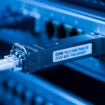
From a standards perspective, Ethernet link rates and lane behaviors follow IEEE 802.3 families for 100G and 50G-class implementations, while vendor optics must align with the host’s SerDes expectations. In practice, “50G vs 100G” is often less about the optics alone and more about whether your switch ports support the same breakout mode, coding, and FEC settings you intend to run. If you plan to use optics with digital diagnostics, you also need DOM support that matches your monitoring tooling.

Technical specs that actually change the decision
Engineers usually compare reach and connector type first, then power and temperature range. For AI workloads, power matters because 100G optics can be installed in large quantities across leaf and spine switches. Thermal limits also matter in dense racks with constrained airflow, where a transceiver that is “spec compliant” on paper can still throttle or fail under real conditions.
Below is a representative comparison of common transceiver classes used in data centers. Actual module behavior depends on the vendor, DSP generation, and whether you run specific FEC profiles.
| Spec | 50G Transceiver (example class) | 100G Transceiver (example class) |
|---|---|---|
| Typical data rate | 50G (often 1x50G or 2x25G depending on platform) | 100G (often 1x100G) |
| Common optics types | SR-style multimode, sometimes LR-style single-mode | SR-style multimode, sometimes LR/ER-style single-mode |
| Typical reach (MMF) | ~70m to 100m depending on OM4/OM5 and vendor | ~100m to 150m depending on OM4/OM5 and vendor |
| Typical reach (SMF) | Varies widely (tens to hundreds of km for LR/ZR families) | Varies widely (LR/ER/ZR families) |
| Power draw (typical) | Often around 1.5W to 3.5W | Often around 2.5W to 5.0W |
| Connector / cabling | LC (most SR optics) | LC (most SR optics) |
| Operating temperature | Commercial or extended; commonly 0C to 70C | Commercial or extended; commonly -5C to 70C or 0C to 70C |
| Form factor | Common: QSFP-based or vendor-specific 50G pluggables | Common: QSFP28/CFP2-class depending on switch generation |
When you compare specific products, look at the vendor datasheet for wavelength, fiber requirements (OM4 vs OM5), and the supported FEC mode. For example, a typical 100G SR module such as Finisar FTLX8571D3BCL is designed for short-reach multimode operation, while a 50G SR module from the same ecosystem may target a similar fiber class but different lane mapping and power profile. For third-party compatibility, check vendor lists and the module’s compliance to the platform’s supported transceiver standards.
Authority references: IEEE Ethernet rate families and link behavior are rooted in IEEE 802.3, while optical and electrical interfaces follow pluggable module guidance and vendor datasheets. For general transceiver requirements and host behavior, see IEEE 802.3 Standards and vendor documentation, plus your switch OEM compatibility matrix.
Decision checklist: picking 50G vs 100G for AI scaling
Use this ordered checklist during planning, not during an outage. It is designed to prevent the common “we bought optics, but the switch rejected them” failure mode.
- Distance and fiber grade: confirm OM4 vs OM5, expected link budget, and any patch panel losses.
- Switch port compatibility: verify the exact port type supports the transceiver’s electrical mode and breakout behavior.
- FEC and encoding alignment: ensure both ends agree on the FEC profile and link training behavior.
- DOM and monitoring integration: check that your network management system reads vendor DOM fields correctly.
- Operating temperature and airflow: validate with rack airflow measurements and module temperature specs.
- Upgrade path and vendor lock-in risk: evaluate whether you can mix OEM and third-party optics without surprise incompatibilities.
- Power and thermal budget: sum transceiver power across all ports and confirm your power distribution and cooling can absorb the delta.
Pro Tip: In many AI fabrics, the practical limiter is not raw link rate but oversubscription plus microbursty latency. If your congestion events correlate with specific ToR uplink groups, moving from 50G to 100G on only the uplink tiers can outperform a full replacement, because it targets the bottleneck where queue growth is happening.

Real deployment scenario: leaf-spine AI cluster planning
Consider a 3-tier leaf-spine topology in a medium AI training environment: 48-port ToR switches feeding 16-port spine uplinks, with each leaf having 8 uplinks at short reach. You run 8K image batches with mixed precision, and you see frequent microbursts during gradient all-reduce phases. Initially, you deploy 50G SR optics on leaf uplinks to increase link count per rack and keep power within a 20 kW per-rack budget. After workload growth, you observe sustained utilization above 70% on uplink groups, and queue occupancy spikes during synchronization windows.
Instead of replacing everything, you upgrade only the uplink tier to 100G SR optics where the bottleneck sits. In the same cabling footprint, you may reduce the number of uplinks per leaf while increasing per-link headroom, which can lower the number of active queues and reduce packet loss under burst conditions. Field measurements typically include per-port error counters, link flaps, and optical diagnostics like received power; you validate that the transceivers remain within vendor thresholds across a full day of temperature variation. This approach often improves training throughput without triggering a full optics refresh cycle.
Common pitfalls and troubleshooting tips
Even experienced teams hit these problems because optics compatibility is a multi-variable system: host SerDes behavior, fiber quality, and optics firmware all interact.
- Pitfall 1: Link comes up at low speed or not at all
Root cause: transceiver electrical mode mismatch, unsupported FEC, or host firmware not recognizing the module.
Solution: update switch firmware, verify supported optics in the OEM compatibility list, and confirm the port profile (including FEC) matches the transceiver’s documented behavior. - Pitfall 2: High CRC/errors after installation
Root cause: fiber polarity mistakes, dirty LC connectors, or patch panel loss exceeding the module budget.
Solution: clean connectors with approved procedures, verify polarity, check received optical power via DOM, and re-test with an optical power meter or OTDR when needed. - Pitfall 3: Intermittent flaps under heat
Root cause: airflow short-circuiting, transceiver temperature rising above the module’s operational limits, or a fan tray issue.
Solution: measure module temperature and compare to datasheet limits, validate front-to-back airflow, and log events alongside rack temperature sensors. - Pitfall 4: DOM shows zeros or alarms
Root cause: DOM field mapping differences between OEM and third-party optics, or monitoring software expecting specific vendor ranges.
Solution: confirm DOM compatibility, adjust monitoring thresholds, and test one module in a controlled environment before broad rollout.

Cost and ROI: what you should budget for 50G vs 100G
Pricing varies by vendor, lead time, and whether you buy OEM vs third-party. In many markets, 100G optics cost more per module than 50G optics, and they also tend to be higher power, which can slightly increase cooling and power distribution costs at scale. However, 100G can reduce the number of active uplinks or simplify oversubscription strategies, which can lower switching port utilization pressure and reduce the need for additional hardware refresh cycles.
For TCO, include: optics purchase cost, expected failure rate (field history and warranty coverage), downtime risk, and operational labor. A realistic planning assumption is to model not just power draw per module but also the probability of incompatibility when mixing vendors. OEM optics often cost more, but third-party can be a strong ROI choice if you validate compatibility for your exact switch model and firmware revision.
As you evaluate options, cross-check OEM datasheets and compatibility guides. For transceiver electrical and optical performance expectations, rely on vendor documentation and IEEE 802.3 behavior for Ethernet link operation: IEEE 802.3 Standards.
FAQ
Is 50G enough for most AI training clusters?
Often yes for smaller clusters or when your fabric is not heavily oversubscribed. If your uplinks show persistent congestion during all-reduce windows, you may need 100G on the bottleneck tiers.
Do 50G and 100G optics use the same fiber types?
They can