Leaf-spine networks often hit a painful tradeoff: you can standardize on 25G SFP28 and scale ports with breakouts, or you can move to 100G QSFP28 uplinks and simplify cabling. This article helps network engineers, field reliability staff, and procurement teams choose between 25G SFP28 vs 100G when you are deciding between 100G native optics and a 4x25G breakout strategy. You will get practical selection criteria, a troubleshooting section based on real failure modes, and a cost and TCO note grounded in operational experience.

Why leaf-spine design choices matter more than port speed
In a leaf-spine topology, the optics decision affects not only throughput but also cabling density, power draw, switch ASIC oversubscription behavior, and field maintainability. A common pattern is 48-port ToR switches feeding spine switches, with uplinks designed for predictable latency and consistent oversubscription. If you choose 100G QSFP28, you typically deploy native 100G links; if you choose 25G SFP28, you may use 4x25G breakout to increase the number of parallel paths or to match port availability on the switch. IEEE 802.3 defines the Ethernet physical layer behaviors that vendors implement for these optics classes, but the operational reality is driven by how your switch ports map to optics and how your transceiver firmware handles diagnostics.
Breakout vs native optics: what changes in the field
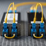
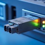
With 4x25G breakout, one physical cable assembly or MPO/MTP fanout can carry four lanes, and the switch presents four logical 25G interfaces. This can improve utilization when you have spare 25G-capable lanes but limited 100G-capable ports, or when you want finer-grained routing and failure isolation between lanes. With native 100G QSFP28, each link is a single interface, which can simplify L3/L2 design but may increase the impact of a single module failure if you rely on one uplink per topology tier.
Key optics specs to compare: reach, wavelength, and power
When comparing 25G SFP28 vs 100G, you should start with the optics family and physical layer characteristics. Most modern leaf-spine deployments use short-reach multimode fiber (OM4 or OM5) for distances within a data hall, and both SFP28 and QSFP28 are available in 850 nm nominal VCSEL-based transceivers. However, vendor power targets, temperature ratings, and connector type can vary, and those differences show up in thermal margins and in MTBF assumptions during stress testing.
| Spec | 25G SFP28 (850 nm SR) | 100G QSFP28 (850 nm SR4) |
|---|---|---|
| Data rate | 25.78125 Gb/s (nominal 25G) | 103.125 Gb/s (100G Ethernet) |
| Wavelength | 850 nm (SR) | 850 nm (SR4) |
| Fiber type | OM3/OM4/OM5 multimode | OM3/OM4/OM5 multimode |
| Typical reach | Up to 100 m on OM4 (depends on vendor) | Up to 100 m on OM4 (depends on vendor) |
| Connector | LC duplex (common for SFP28) | MPO/MTP (common for SR4) |
| Tx power / Rx sensitivity | Vendor-specific; affects link margin | Vendor-specific; SR4 requires lane-level margin |
| Operating case temperature | Often 0 to 70 C or wider options | Often 0 to 70 C or wider options |
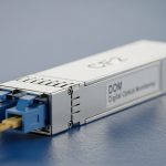
| Diagnostics | DOM over I2C (vendor implementation) | DOM over I2C (vendor implementation) |
| Form factor | SFP28 1x (single channel) | QSFP28 4-lane bundle |
In practice, two optics from different vendors can both claim 100 m reach but still behave differently under real plant conditions. Plant conditions include patch cord aging, dirty connectors, bend radius compliance, and modal bandwidth variations between OM4 and OM5. For reliability planning, treat link budget and thermal behavior as first-class inputs, not marketing reach. If you are validating, align your test method with vendor guidance and the general Ethernet physical layer performance expectations referenced in IEEE 802.3.
Concrete module examples you may see in procurement
In many shops, you will see OEM-branded and third-party equivalents. Examples include Cisco SFP-10G-SR for older 10G, but for your 25G SFP28 and 100G QSFP28 needs, engineers commonly evaluate modules like Finisar and FS.com SR optics. For instance, you may encounter Finisar FTLX8571D3BCL (25G class SR variant depending on exact part), and FS.com listings such as SFP-25G-SR or QSFP-100G-SR4 variants for OM4. Always confirm the exact part number, DOM support, and switch compatibility before ordering at scale. [Source: IEEE 802.3 Ethernet physical layer specifications]

Decision checklist: choosing 25G SFP28 vs 100G for leaf-spine
Use this ordered checklist during design sign-off and procurement. It is written for engineers who must balance performance, maintainability, and reliability. You can treat it as a lightweight ISO 9001 style control plan: define acceptance criteria, verify compliance, and document exceptions.
- Distance and fiber plant quality: confirm OM4/OM5 type, measure end-to-end loss, and ensure bend radius and connector cleanliness. If your plant is near the margin, prefer the option with better measured link stability.
- Switch port mapping and breakout support: verify that your leaf and spine models support 4x25G breakout on the exact physical ports you plan to use, and that the breakout mode is officially supported by the vendor.
- Budget and optics availability: price optics per interface, not per module. A 100G QSFP28 can cost more than four 25G SFP28 optics, but the total number of required modules and fanouts may shift the true cost.
- DOM and telemetry compatibility: check whether the switch reads DOM thresholds correctly and whether vendor-specific alarms are mapped to your monitoring system. Misinterpreted DOM can cause false positives or missed degradation.
- Operating temperature and airflow: validate case temperature rating and check that the switch airflow model keeps optics within spec at full load. Power dissipation differences can change local hotspot temperatures.
- Vendor lock-in and spares strategy: evaluate OEM vs third-party risk. If a module is not on the approved list, you may lose support and increase downtime during RMAs.
- Failure isolation and MTBF planning: consider whether you prefer one 100G interface carrying all traffic or four 25G lanes that may fail independently due to lane-level issues, dust, or connector problems.
Pro Tip: In SR4 implementations, a “clean link” can still fail intermittently if one of the four lanes has lower margin due to a slightly mis-seated MPO connector. During acceptance tests, verify lane-level diagnostics (where available) and re-check optical connector seating after any patch cord change, even if the link comes back up.
Real-world leaf-spine scenario: 48-port ToR to 3 spine racks
Consider a data center with a 3-tier leaf-spine design: 48-port ToR switches at the leaf, each with 4 uplinks to a pair of spine switches per leaf for a total of 8 uplinks per leaf. Suppose the leaf has limited native 100G ports but supports 4x25G breakout on specific quad-capable slots. In a typical deployment, you might run OM4 fiber with a target of 70 m average reach including patch cords, and you budget for an additional 3 dB margin to account for connector aging. The network team wants consistent ECMP behavior and fast troubleshooting. In this scenario, choosing 25G SFP28 with breakout can match the switch’s available lanes and improve failure isolation: if one 25G lane degrades, you can shift traffic patterns or replace the affected connector path without taking the entire 100G uplink down.
On the other hand, if your spine supports abundant native 100G QSFP28 and your cabling plant already uses MPO trunks with good lane balancing, native 100G can reduce the interface count and simplify the monitoring dashboards. Engineers often find that native 100G reduces operational overhead for link-level events because there are fewer logical interfaces to correlate. The “best” choice is therefore not just a speed comparison; it is a systems integration decision involving optics, switching ASIC lane mapping, and your operational runbooks.

Common mistakes and troubleshooting outcomes
Reliability issues usually come from repeatable failure modes. Below are concrete pitfalls you can prevent during rollout and during maintenance windows.
Connector cleanliness and MPO seating errors
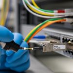
Root cause: dirty LC or MPO endfaces and incomplete seating cause attenuation spikes and lane-specific degradation. SR optics are sensitive to endface contamination and connector geometry, and MPO SR4 can show lane asymmetry if the ferrules are not aligned. Solution: use certified cleaning tools, re-terminate or replace patch cords if needed, and re-seat MPO cassettes after any movement of the trunk. After cleaning, observe DOM optical power and error counters for several minutes before declaring stability.
Assuming breakout works identically across switch models
Root cause: some switches support 4x25G breakout only on specific port groups and may require configuration changes, optics types, or specific firmware versions. Using an unsupported breakout mode can lead to link flaps, negotiated speed fallback, or interfaces that remain administratively down. Solution: verify the exact port mapping in the vendor hardware guide, confirm firmware compatibility, and test one leaf and one spine pair in a staging environment before scaling.
Ignoring temperature and airflow margins during peak load
Root cause: QSFP28 modules can run warmer than expected in constrained airflow, especially with higher transmit power settings. If your rack layout blocks front-to-back airflow or if fan speeds drop during certain thermal states, you may see rising errors and eventual link drops. Solution: measure inlet air temperature and confirm optics case temperature stays within the module specification. Add an acceptance test that includes a sustained traffic load while monitoring temperature and optical power thresholds.
Treating reach as identical across vendors
Root cause: vendors use different receiver sensitivity targets, power budgets, and compliance margins. Two modules with “100 m on OM4” claims can behave differently with your exact patch cords and splice losses. Solution: validate with your plant: run OTDR or at least end-to-end loss verification, test with representative patch cords, and document which module part numbers pass. For critical links, keep a spare tested module on site.
Cost and ROI: module price is not the whole story
In many procurement environments, 25G SFP28 optics and their third-party equivalents are priced lower per module than 100G QSFP28 optics. However, ROI depends on total cost of ownership: number of modules, number of patch cords and fanouts, spares strategy, and downtime cost during failures. In a typical mid-size data center, OEM modules might cost roughly two to four times a third-party module price, but OEM can reduce compatibility risk and RMA friction. Third-party optics can still be cost-effective if they are on the approved list and validated in staging.
From a reliability perspective, you should treat MTBF as a planning input rather than a guarantee. If you cannot obtain vendor reliability data, use accelerated stress testing internally (temperature cycling, link error monitoring, and connector cleaning discipline) and track field return rates by module serial number. Even if two transceivers have similar nominal MTBF, the real differentiator is how often your environment triggers optical degradation: dust exposure, airflow variability, and patching frequency. For short-reach leaf-spine, the ROI often favors the option that your team can install and troubleshoot fastest with the fewest “unknown unknowns.”
FAQ
Is 25G SFP28 better than 100G QSFP28 for leaf-spine uplinks?
It depends on switch port availability and whether you can use 4x25G breakout cleanly. If you have limited native 100G ports or want finer failure isolation, 25G SFP28 can be advantageous. If your spine and monitoring workflows are optimized for native 100G, 100G QSFP28 may reduce interface count and operational complexity.
Can I use 25G breakout and still run 100G end-to-end?
End-to-end consistency requires that both ends agree on the interface type and configuration. Breakout changes the logical interface structure, so it is not always compatible with a native 100G peer on the other side unless the switch supports a mapping that your design requires. Always validate with the exact vendor hardware and firmware combination.
What fiber should I choose for SR: OM4 or OM5?
For typical distances within a data hall, OM4 is common and provides reliable performance for 850 nm SR optics. OM5 can improve wavelength-division optical performance for certain future-ready systems, but your current SR optics must be explicitly compatible. Measure your plant loss and verify connector cleanliness regardless of OM type.
How do DOM diagnostics affect troubleshooting?
DOM provides telemetry such as optical power and temperature, but the interpretation is vendor-specific. If your monitoring system thresholds are not aligned with the module behavior, you can miss early degradation or trigger noisy alerts. Validate DOM readings during staging and tune alarms based on observed baselines.
Are third-party optics safe for production?
They can be, but only if they are on the approved interoperability list and validated in your environment. The risk is not just functional link establishment; it is also long-term stability, DOM compatibility, and RMA handling. For critical spine uplinks, many teams keep a smaller set of OEM optics as a fallback.
What should I test before scaling to hundreds of links?
Test one full path end-to-end with your representative patch cords, confirm link stability under sustained traffic, and verify that errors remain near zero after connector events. Also test during thermal stress by running peak load and observing temperature and DOM trends. Document results per module part number and firmware revision so you can reproduce success.
By comparing 25G SFP28 vs 100G through reach, power, port mapping, and operational failure modes, you can choose optics that match your leaf-spine constraints rather than just your target bandwidth. Next, review your vendor’s breakout compatibility matrix and run a staging validation with your real patch cord assemblies using the checklist above. optics compatibility and DOM monitoring
Author bio: I have deployed and validated short-reach Ethernet optics in leaf-spine data centers, focusing on acceptance testing, link margin verification, and field failure analysis. I also work with reliability engineering practices to estimate MTBF risk, define spares strategy, and improve operational processes aligned with quality management systems.