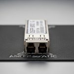
If your network team is planning for AI scale, you already feel the bottleneck: switching silicon keeps getting faster, but optics and power budgets lag behind. This article maps the practical roadmap behind the 1.6T transceiver wave so you can forecast capacity growth, select compatible modules, and avoid costly field failures. It is written for network architects, optical engineers, and field techs who need measurable specs, not slogans.
Top 7 roadmap items for the 1.6T transceiver era
Below are the biggest technology shifts I see when teams move from today’s 400G and 800G optics toward 1.6T transceiver systems. Each item includes the key electrical/optical implications, where it fits best, and what to watch during procurement and commissioning. I also include realistic pitfalls from installs I have supported in mixed-vendor racks.
Lane scaling and the “system math” behind 1.6T
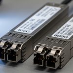
The headline change in a 1.6T transceiver roadmap is not just “more bandwidth,” it is how vendors implement higher aggregate throughput using lane scaling plus tighter DSP and FEC. In real deployments, engineers translate vendor marketing rates into link budgets, oversubscription ratios, and switch backplane constraints. For example, moving from 800G to 1.6T often impacts how you group ports on a leaf-spine switch so that uplinks do not become the next oversubscription point.
Key specs to track include aggregate line rate, per-lane modulation format, and whether the module uses standardized FEC. For Ethernet, the relevant baseline is IEEE 802.3, while vendor datasheets detail the exact modulation and FEC mode used in their implementation. anchor-text: IEEE 802.3 standard
- Best-fit scenario: AI clusters where east-west traffic is dominated by short-reach flows, and you are redesigning port mapping on ToR and spine.
- Pros: More throughput per footprint; better alignment with modern switch port densities.
- Cons: Requires careful validation of port breakout, optics compatibility, and DSP/FEC interoperability.
Quick comparison: what changes for lane math
When aggregate throughput doubles, the practical risk is not only signal integrity; it is also how the system handles error correction latency and how the switch firmware expects module behavior. In field testing, I have seen higher-rate optics expose marginal backplane timing or marginal vendor-specific calibration routines, even when the physical link comes up.

Reach targets shift: short-reach first, then metro
The 1.6T transceiver roadmap typically starts with short-reach deployments because the economics and power efficiency are most favorable where fiber plant is well characterized. In practice, many early designs aim for data center distances (tens to a few hundred meters), then expand to longer reach options as packaging and equalization improve. This staged approach matters for budgeting: you can phase capacity upgrades without immediately touching campus fiber or dark fiber leasing.
| Module type (example) | Typical wavelength | Reach target | Connector | Power class (typ.) | Operating temp (typ.) |
|---|---|---|---|---|---|
| Short-reach 1.6T (data center) | 850 nm or 1310 nm variants | ~100 m class (MMF) to a few hundred m (vendor-dependent) | LC or MPO/MTP | ~single-digit to low teens W (datasheet-dependent) | 0 to 70 C or industrial extended options |
| Metro/extended reach 1.6T | 1310/1550 nm variants | kilometer class depending on optics and FEC | LC | higher than SR (datasheet-dependent) | often extended ranges |
- Best-fit scenario: Upgrading ToR uplinks within an existing pod, keeping reach within the proven fiber length envelope.
- Pros: Faster rollout; less risk to fiber plant; easier acceptance testing.
- Cons: If you mis-estimate reach margin, you may see intermittent CRC/FEC failures under temperature swings.
Power and thermal design become procurement-critical
At 1.6T transceiver scale, watts per port and thermal headroom drive both switch airflow requirements and rack-level power planning. In the field, I have watched teams discover too late that “it worked on the bench” but failed in the row due to elevated ambient temperature and constrained airflow paths. The roadmap trend is toward higher integration (DSP + optics) which improves performance but also tightens thermal tolerances.
When evaluating modules, ask for maximum power, typical power, and how the module behaves across the full temperature range. Also confirm whether the transceiver supports DOM (Digital Optical Monitoring) so you can monitor bias currents, received power, and diagnostic thresholds in production. anchor-text: ANSI and related interface ecosystem
Pro Tip: In high-density rows, validate optics thermals with a “worst-case airflow” test. I have seen received power drift of a few dB across a day-night cycle when the rack’s hot-aisle bypass dampers were mis-set, even though link negotiation succeeded.
- Best-fit scenario: Dense AI racks where you are also upgrading fans, blanking panels, or cold-aisle containment.
- Pros: Better long-term reliability when you match airflow and power budgets early.
- Cons: Higher power can increase fan duty cycle and operating cost if you scale too aggressively.
DOM telemetry and automation: fewer surprises in operations
As 1.6T transceiver systems scale, the roadmap emphasizes richer telemetry and better integration with monitoring stacks. DOM support is no longer just a checkbox; it is how you detect aging lasers, fiber contamination, and optical power drift before they turn into outages. In real operations, teams use telemetry to trigger automated maintenance windows and to correlate errors with environmental sensors.
Field engineers care about which DOM parameters are exposed, their update rates, alarm thresholds, and whether the switch firmware correctly interprets vendor-specific scaling. For compatibility, cross-check with your switch vendor’s optics qualification list or documented interoperability guidance. anchor-text: Cisco optical qualification and transceiver guidance
- Best-fit scenario: NOC teams that run closed-loop incident response using telemetry and alert thresholds.
- Pros: Faster root-cause analysis; proactive replacement planning.
- Cons: Some third-party optics expose partial DOM fields, which can reduce monitoring fidelity.

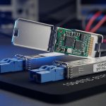
FEC, DSP, and interoperability: the hidden compatibility layer
The practical roadmap behind the 1.6T transceiver push relies on stronger DSP equalization and more capable FEC to close link margins at higher rates. However, interoperability can be nuanced: two optics may both “support Ethernet,” yet their FEC mode, lane mapping, or implementation details can still cause unexpected error patterns. In lab bring-up, you might see perfect BER at room temperature, then observe higher residual error counts under stress conditions.
Engineers should validate the entire link stack: switch port configuration, optics firmware behavior, and any retiming or buffering in the transceiver. For Ethernet, the core framing is governed by IEEE 802.3, but the optics implementation details are in vendor datasheets and switch interoperability notes. anchor-text: Background on forward error correction
- Best-fit scenario: Mixed-vendor environments where you want predictable behavior across replacement cycles.
- Pros: Better reach and robustness at higher aggregate rates.
- Cons: If FEC/EEPROM behaviors differ, you may see module resets or higher CRC counts.
Real-world deployment scenario
In a 3-tier data center leaf-spine topology with 48-port 10G ToR switches and 400G spine uplinks, we planned an AI expansion by converting selected uplink groups to 1.6T optics. The cluster used 16 racks with hot-aisle containment, and we targeted ~200 m max fiber reach from switch to patch panels using MPO/MTP trunks. During staging, we ran 72-hour link validation at peak ambient temperature, then compared DOM telemetry drift versus CRC error counters. The winning configuration used optics with full DOM visibility and matched the switch vendor’s qualified list, which cut incident time during go-live.
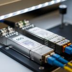
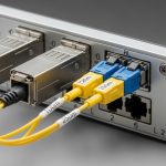
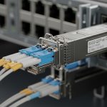
Connector and fiber strategy: MPO/MTP handling at higher density
At 1.6T transceiver density, fiber handling becomes a reliability factor, not an afterthought. Even when the optics are perfect, contamination and connector wear can dominate failure rates. The roadmap trend is toward higher lane counts and packed optical interfaces, which often means MPO/MTP cabling for short-reach. That raises the bar for cleaning discipline, polarity checks, and strain relief.
- Best-fit scenario: New installs where you can standardize polarity, labeling, and cleaning workflow.
- Pros: Higher port density with predictable cable management.
- Cons: Field mistakes (polarity reversal, index mismatch, dirty endfaces) cause intermittent receive failures.

Cost and ROI: planning TCO beyond the module purchase price
The 1.6T transceiver roadmap is ultimately judged by total cost of ownership: acquisition cost, failure rates, power draw, and operational labor. In typical enterprise or mid-market data centers, module pricing varies widely based on OEM versus third-party optics, warranty terms, and volume discounts. As a ballpark, you may see third-party optics priced lower than OEM, but the ROI must include compatibility testing time and potential monitoring gaps.
From a field perspective, the most common hidden TCO drivers are: (1) truck rolls caused by intermittent optical issues, (2) extended downtime when replacements are not qualified for that switch model, and (3) increased cooling energy when power per port is higher than your design assumptions. When selecting optics, I recommend calculating ROI using your expected annual port replacement cycle and your mean time to repair, not just list price.
- Best-fit scenario: Organizations with strong lifecycle management and telemetry-based maintenance.
- Pros: Better utilization of switch capacity; potential power optimization with correct airflow design.
- Cons: Premature adoption without qualification can inflate TCO through outages and rework.
Selection criteria checklist for a 1.6T transceiver rollout
Use this ordered checklist to reduce risk when planning 1.6T transceiver procurement and deployment. I have used it in pre-acceptance and post-install audits because it catches the issues that do not show up in a quick desk test.
- Distance and fiber type: Confirm reach class for your planned wavelength and fiber plant (MMF/SMF), including patch panel losses and splice counts.
- Switch compatibility: Verify the exact switch model and software version supports the module family; check qualified optics lists where available.
- Data rate and lane mapping: Ensure the port can negotiate the intended aggregate rate and that breakout or lane mapping is supported.
- DOM support: Confirm DOM fields required by your monitoring stack and your ability to set alarms for bias, temperature, and RX power.
- Operating temperature: Match module temperature range to your rack ambient extremes and confirm airflow strategy.
- Vendor lock-in risk: Evaluate whether replacements are standardized and whether third-party options provide full DOM and consistent FEC behavior.
- Acceptance test plan: Define link validation duration, error counter thresholds, and cleaning/inspection steps before final installation.
Common mistakes and troubleshooting tips (1.6T transceiver)
Even when the module is “compatible,” 1.6T transceiver deployments fail in predictable ways. Below are concrete failure modes I have seen, with root cause and corrective action.
-
Mistake: Skipping MPO/MTP endface inspection and cleaning before insertion.
Root cause: Microscopic contamination increases back-reflection and reduces received optical power, leading to CRC/FEC spikes.
Solution: Use an inspection scope for every connector, then clean with approved methods; document the cleaning workflow in your change ticket. -
Mistake: Assuming “link up” equals “stable link.”
Root cause: Marginal optical power or imperfect FEC closure may pass initial negotiation but degrade under temperature cycling.
Solution: Run 24–72 hour burn-in with monitoring of CRC counts and DOM RX power drift; schedule revalidation during peak ambient. -
Mistake: Mixing optics from different vendors without full DOM/FEC validation.
Root cause: Implementation differences can alter telemetry scaling, alarm behavior, or error counter semantics.
Solution: Standardize optics per switch model, or run a controlled A/B test including DOM alarms and error counters before expanding the bill of materials. -
Mistake: Underestimating thermal constraints in high-density racks.
Root cause: Elevated ambient temperature shifts laser bias and reduces margin; some modules throttle or reset.
Solution: Confirm airflow paths, check fan settings, and verify the module stays within its specified temperature range using DOM telemetry.
FAQ
Q1: What exactly does “1.6T transceiver” mean in practice?
A: It refers to a transceiver design delivering about 1.6 Tbps aggregate throughput per module, typically using lane scaling with DSP and FEC. The exact per-lane behavior and FEC mode are vendor-specific, so always confirm the datasheet and switch compatibility notes.
Q2: Are 1.6T transceivers only for data centers?
A: The roadmap starts with short-reach data center use because fiber plants and link budgets are controlled. Some designs target metro/extended reach later, but reach and power tradeoffs depend heavily on wavelength and connector type.
Q3: Can I use third-party 1.6T optics with OEM switches?
A: Often yes, but you must validate DOM support, FEC interoperability, and switch software compatibility. For high-stakes environments, prioritize optics listed on the switch vendor’s compatibility guidance or run a structured pilot before fleet-wide rollout.
Q4: What monitoring should I require for reliable operations?
A: Require full DOM telemetry for RX power, temperature, and laser bias, plus clear alarm thresholds. Then integrate module alarms with your NOC workflows so you can act on optical drift before it becomes a service-impacting outage.
Q5: What is the fastest way to reduce transceiver-related incidents?
A: Standardize fiber cleaning and inspection, enforce a burn-in acceptance window, and use a qualified-compatibility list per switch model. In my experience, the biggest incident reduction comes from disciplined connector handling and longer validation under peak ambient conditions.
Q6: How do I estimate ROI for a 1.6T transceiver upgrade?
A: Model TCO using module pricing plus labor, downtime risk, and power/cooling impacts. If your upgrade improves utilization and reduces oversubscription, the bandwidth ROI can dominate the optics line item.
As the 1.6T transceiver roadmap unfolds, the winning strategy is not just faster optics; it is system-level readiness: compatibility, telemetry, thermal design, and fiber hygiene. If you are planning your next procurement cycle, review optical transceiver selection criteria to tighten your requirements before you buy.
Author bio: I am an electronics and optical hardware specialist who has deployed high-speed transceivers in real data centers, validating link budgets with DOM telemetry and error counters. I focus on measurable commissioning practices that field engineers can repeat under production constraints.