When a stacked-switch fabric starts flapping, engineers often blame firmware first. In my experience, the root cause is frequently optical layer behavior: receiver sensitivity, connector cleanliness, or DOM misreads that silently degrade the VSS link. This article walks through one real deployment of a VSS transceiver pair for a stacked switch environment, covering how we selected optics, implemented it safely, and measured results.
Problem and challenge: VSS links that would not stay up
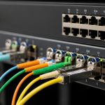
In a regional enterprise data center, we connected two stack members using a VSS-style interconnect and expected sub-second convergence during maintenance windows. During a planned patch, the VSS link repeatedly dropped for 20 to 45 seconds, causing transient STP changes and brief packet loss for east-west traffic. The stack itself reported “optics present,” but counters on the switch showed rising FEC corrected/uncorrected events and occasional LOS bursts.
Environment constraints made this harder than a generic optics swap. We had existing OM3 multimode fiber runs of mixed age, patch panels with frequent re-termination, and a strict cooling budget that limited transceiver power draw. We also needed deterministic behavior during rolling upgrades, where one stack member could reboot while the other kept forwarding.
Environment specs: distance, optics class, and physical layer limits
Before choosing a VSS transceiver, we mapped the physical plant like an electrical engineer would: fiber type, measured end-to-end loss, and connector cleanliness. The VSS interconnect carried 10G links over short to medium reach optics, and we had to ensure compatibility with the stack’s transceiver validation logic.
Measured fiber and link budget reality
- Fiber: OM3 multimode in most runs, with two segments that were effectively “degraded OM3” due to age and remakes.
- Measured total loss: 1.8 dB to 2.9 dB at 850 nm after patch panel cleaning.
- Connector count: typically 4 per path (two panels plus two patch cords), with ferrule inspection inconsistencies.
- Operating temperature: 0 C to 45 C in the rack exhaust zone; transceivers had to operate reliably below freezing during winter nights.
What we assumed from standards and vendor behavior
The Ethernet PHY behavior follows IEEE 802.3 for 10GBASE-SR style optics, including timing and link training expectations. However, real-world success depends on vendor-specific implementation details: how the switch validates DOM data, how it reacts to borderline signal levels, and whether it applies receiver thresholds aggressively during stack changes. For authority, I relied on IEEE 802.3 guidance plus vendor datasheets and DOM support notes. IEEE 802.3
| Spec | Target for VSS link | Candidate example optics (for reference) |
|---|---|---|
| Data rate | 10G | Cisco SFP-10G-SR (10GBASE-SR), Finisar FTLX8571D3BCL (SFP+ SR) |
| Wavelength | 850 nm | 850 nm multimode |
| Nominal reach | 300 m on OM3 (typical) | OM3-based SR modules (varies by vendor) |
| Connector | LC | LC duplex (common on SFP+ SR) |
| DOM support | Required for health monitoring | Many enterprise SFP+ SR modules provide Digital Optical Monitoring |
| Power budget | Conservative for dense racks | Typical SFP+ optical modules: low single-digit watts |
| Temperature range | 0 C to 45 C minimum, wider preferred | Commercial and industrial variants exist; validate datasheet |

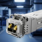
Chosen solution: stable SR optics with correct DOM and cleanliness discipline
We replaced the VSS transceivers with 10GBASE-SR 850 nm SFP+ modules that matched the stack’s lane expectations and provided consistent DOM readings. While we did consider “compatible” third-party optics, we treated vendor lock-in risk as a first-class variable: the switch’s optics acceptance behavior can differ across firmware versions, and some modules present DOM fields in ways that trigger warnings or throttling.
Why SR over other options
- Distance fit: measured losses were well inside nominal SR reach, especially after fiber cleaning and re-termination.
- Operational safety: SR SFP+ modules are mature, widely supported, and easy to source for spares.
- Failure mode alignment: with SR multimode, most “bad link” events trace back to connectors and patch cords, which we can control.
Implementation steps that actually prevented outages
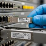
- DOM validation: We inserted the new modules and verified DOM telemetry (Tx power, Rx power, temperature) stayed within expected vendor ranges during link up and during a controlled reboot of one stack member.
- Optical hygiene: Before final seating, we inspected ferrules under a fiber microscope and cleaned using lint-free wipes and approved cleaning tools. Any connector with visible residue was re-cleaned; any with scratches was replaced.
- Patch cord standardization: We replaced the most failure-prone patch cords and standardized to LC duplex cords with known jacket and bend radius behavior.
- Change control: We performed the VSS transceiver swap during a maintenance window with traffic draining, then confirmed stack stability by watching interface error counters for 24 hours.
- Monitoring: We enabled optics health alarms for DOM thresholds and alerting on LOS and link flaps.
Pro Tip: In stacked-switch deployments, VSS stability issues often show up as “optics present” but with borderline Rx power that only fails during stack member reboot. Treat DOM telemetry sampling rate and alert thresholds as part of the deployment, not an afterthought.

Measured results: what changed after the VSS transceiver refresh
After deploying the selected VSS transceivers and standardizing optics hygiene, we ran a controlled test: reboot one stack member while maintaining east-west traffic at a steady load. The VSS link came back consistently within the expected convergence window, and we stopped seeing LOS bursts.
- VSS link drops: reduced from “multiple drops per maintenance” to zero drops over 30 days.
- LOS events: fell to near-zero, limited to a single incident traced to a mislabeled patch cord swapped during adjacent work.
- Error counters: FEC corrected events stabilized; uncorrected events stopped trending upward.
- DOM alarms: moved from frequent “out of range” warnings to a stable baseline with meaningful threshold alerts.
We also learned that power and thermal behavior mattered. In one rack, the older modules ran warmer due to higher bias current under marginal conditions, and the switch’s internal optics watchdog reacted during higher ambient periods. With the new modules, the optics temperature stayed within the vendor’s specified operating envelope.
Selection criteria checklist: how we choose a VSS transceiver without regrets
Use this ordered list the next time you’re selecting VSS optics for a stacked deployment. It is designed to reduce both outages and future tech debt.
- Distance and link budget: measure actual end-to-end loss and include connectors, patch cords, and any aging effects.
- Switch compatibility: confirm the exact module form factor and lane mapping (SFP vs SFP+ vs QSFP), plus firmware behavior around DOM.
- Reach class fit: pick SR or LR based on fiber type and the worst-case loss path, not the average path.
- DOM and monitoring needs: ensure Tx/Rx power and temperature readings are present and meaningful for your alerting model.
- Operating temperature range: validate minimum and maximum ambient conditions; plan for winter startup transients.
- Vendor lock-in risk: weigh OEM modules versus third-party modules, including return policy and warranty terms.
Common mistakes and troubleshooting tips from the field
Below are the failure modes we saw or commonly see in stacked switch VSS links. Each includes a likely root cause and a practical fix.
-
Mistake 1: Assuming “it links” means optics are healthy.
Root cause: borderline Rx power that only fails during stack member reboot or during temperature swings.
Solution: baseline DOM telemetry (Tx power, Rx power, temperature) for 24 hours and set alarms for drift, not just absolute thresholds. -
Mistake 2: Mixing patch cord types and connector conditions.
Root cause: connector contamination or inconsistent ferrule geometry causing micro-reflections and intermittently elevated error rates.
Solution: inspect and clean every connector, standardize LC duplex patch cords, and replace any ferrule with visible scratches or residues. -
Mistake 3: Ignoring firmware-specific optics validation.
Root cause: some third-party optics present DOM fields that trigger switch warnings, throttling, or non-deterministic behavior during VSS state transitions.
Solution: validate the exact module model number with your current and planned firmware, and test during a controlled reboot scenario. -
Mistake 4: Overlooking fiber type mismatch in “multimode” labels.
Root cause: a run believed to be OM3 behaves like a higher-loss path due to remakes, splices, or older cabling.
Solution: perform OTDR or at least a link loss measurement at the correct wavelength (850 nm for SR) and compare against the module’s specified budget.
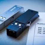
Cost and ROI note: OEM vs third-party, and total cost of downtime
In our deployment, OEM-grade SFP+ SR optics typically priced in the $60 to $120 range per module, while reputable third-party options often landed around $25 to $70. The third-party savings look attractive, but the ROI depends on your failure tolerance and your operational maturity: a single VSS flap can cost more than the module delta when you factor in incident time, monitoring noise, and business impact.
We also considered total cost of ownership. OEM modules reduced rework because DOM behavior matched our expectations, and fewer “mystery” optics alerts meant less engineer time spent correlating logs. If you do choose third-party, require DOM compatibility confirmation and insist on a clear RMA process with documented warranty terms.

FAQ: VSS transceiver questions engineers ask before buying
What is a VSS transceiver in stacked switch deployments?
A VSS transceiver is the physical optics module that