If you are building or expanding a UniFi fiber uplink, the wrong optics can cause link flaps, “transceiver not supported” messages, or silent throughput loss. This article helps network admins and data center field engineers validate a UniFi switch transceiver before you rack it, with practical checks you can perform on day one. You will also get troubleshooting patterns, cost and TCO reality, and a short decision checklist.
Understanding what “compatible” means for a UniFi switch transceiver
On most UniFi managed switching platforms, transceiver compatibility is not only about physical form factor (for example SFP/SFP+ or SFP28). The switch also evaluates electrical signaling, vendor-specific identification, and often Digital Optical Monitoring (DOM) values. In the field, I have seen cases where an optics module negotiated fine at the physical layer but failed DOM polling, leading to alarms and conservative port behavior.
For standards alignment, the general optical behavior follows IEEE 802.3 for link timing and optical signaling, while the module identification and management behavior are documented in vendor datasheets and the SFF Multi-Source Agreement (MSA) for transceiver interfaces. If you are troubleshooting, treat compatibility as a three-part problem: mechanical fit, optical reach and wavelength, and switch acceptance of identification/DOM.
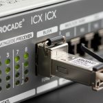
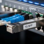
Form factor and signaling: SFP vs SFP+ vs SFP28
First confirm the port type on the UniFi switch model. Many enterprise deployments mix 1G SFP, 10G SFP+, and 25G SFP28 in different chassis generations, and the optics are not interchangeable. A common failure mode is installing a 10G-rated module into a 1G-only cage; the link may never come up or may fall back incorrectly.
DOM and identification checks that matter operationally
DOM typically reports temperature, laser bias, received power, and supply voltage. If a module does not support DOM as expected, the switch may mark it as unsupported even if the optics still transmit. This is why two “same wavelength, same reach” modules from different vendors can behave differently in real UniFi environments.
Pro Tip: Before you patch into production, power-cycle the switch port with the optics installed and watch the first 60 seconds of link state and diagnostics. DOM polling and ID validation often happen right after module insertion; capturing that timeline makes root cause analysis dramatically faster than testing hours later after other changes.

Key specs to verify before you buy: wavelength, reach, power, and temperature
Compatibility guides are useful, but the engineering checks come down to optical and electrical parameters. For example, a 10G SR optics module operates at 850 nm over multimode fiber, while 10G LR uses 1310 nm over single-mode fiber. Selecting the wrong wavelength can still “light” the fiber, but you will see high BER, intermittent drops, or total link failure.
Also confirm operating temperature range and power consumption. In dense racks with high ambient temperature, a marginal transceiver can pass link training once and then fail under sustained load. Vendor datasheets list typical and maximum power, which feeds into your switch power budget and thermal design.
| Spec | Example Module (Typical) | What to Check on Your UniFi Port |
|---|---|---|
| Data rate | 1G, 10G, or 25G (SFP/SFP+/SFP28) | Match port speed; avoid mixing generations |
| Wavelength | 850 nm (SR), 1310 nm (LR), 1550 nm (ER/LR long) | Match fiber type and expected link budget |
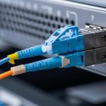
| Connector | LC (most common) | Ensure cage supports LC duplex optics |
| Reach | 850 nm SR: typical up to ~300 m (OM3/OM4 varies) | Validate with your OM grade and measured loss |
| DOM support | Digital Optical Monitoring (vendor dependent) | Confirm switch diagnostics expectations |
| Operating temp | Typically 0 to 70 C (commercial) or wider for some “-T” variants | Verify your rack ambient and airflow profile |
Real-world reach math: don’t guess
Use your fiber plant test results. Pull the measured attenuation (dB/km), connector loss (dB per connection), and any patch panel loss. Then compare against the module’s specified link budget from the datasheet. If you only know “it worked once,” assume the next transceiver may be the one that exposes the weak splice.

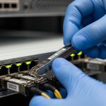
Ubiquiti UniFi Switch Transceiver compatibility workflow (field-tested)
Start with the exact UniFi switch model and port speed. Then cross-check the module form factor, optical type, and DOM behavior against the Ubiquiti compatibility guidance. Finally, validate with a short controlled test: insert optics, observe link state, confirm negotiated speed, and verify received optical power if DOM is available.
Step-by-step checklist you can run in under 10 minutes
- Confirm port type: SFP, SFP+, or SFP28; match the switch’s expected data rate.
- Match optics profile: SR at 850 nm for multimode, LR/ER at 1310/1550 nm for single-mode.
- Validate connector and fiber grade: LC duplex and OM3/OM4 vs OS2 expectations.
- Check DOM support: look for switch diagnostics that mention DOM, temperature, or unsupported optics warnings.
- Verify operating temperature: compare rack ambient and airflow against the module’s specified range.
- Plan for vendor risk: if you must use third-party optics, standardize on one vendor and lot for a pilot.
For external reference on optical and electrical expectations, consult IEEE 802.3 for Ethernet PHY behavior and the SFF MSA documentation for transceiver interface characteristics. Also review the exact vendor datasheet for your module model number, since DOM implementation details are not uniform across manufacturers. [Source: IEEE 802.3 Working Group] IEEE 802.3
Selection criteria decision list for UniFi switch transceivers
When you compare options, do not shop only by reach. In practice, the differentiators are acceptance behavior, DOM compatibility, and thermal stability under your rack conditions. This is especially true in mixed-vendor environments where the switch may accept one brand but reject another even at the same wavelength and data rate.
- Distance and fiber type: OM3/OM4 vs OS2; measured end-to-end loss.
- Switch compatibility signals: official guidance and observed DOM behavior.
- DOM support and alarms: confirm the switch reports temperature and RX power correctly.
- Operating temperature: ensure margin for high-ambient racks.
- Budget and TCO: OEM optics cost more but reduce downtime risk.
- Vendor lock-in risk: third-party can be cheaper, but standardize and pilot first.
Common examples of widely used optics families include Cisco-branded SR/LR SFP/SFP+ modules and compatible optics from reputable vendors such as Finisar/Fiberstore and FS. For instance, a module like Cisco SFP-10G-SR or a comparable third-party SR module (for example from FS.com) may work physically, but DOM and switch acceptance can still vary by UniFi platform and firmware.

Common mistakes and troubleshooting tips
Most transceiver problems are predictable once you know the failure patterns. Below are issues I see during deployments, along with root cause and the fastest corrective action.
Port shows “unsupported transceiver” even though the link seems up
Root cause: DOM or identification fields do not match what the UniFi platform expects, or the module implements DOM differently. Solution: verify DOM support and try a known-compatible module model from the documented compatibility list; update switch firmware if Ubiquiti notes transceiver compatibility improvements. [Source: Vendor datasheets and Ubiquiti guidance]
Link flaps under load after initial success
Root cause: marginal optical budget, bad connectors, or a fiber pair mismatch (duplex polarity issues with LC connectors). Solution: clean connectors with approved methods, re-seat LC ends, confirm correct TX/RX orientation, and measure RX power via DOM if available.
Total link failure after swapping multimode and single-mode optics
Root cause: wrong wavelength-to-fiber pairing (for example 850 nm SR against OS2) or incorrect expected reach for your OM grade. Solution: confirm wavelength and fiber type, then re-run loss budget using measured dB values and the module’s specified link budget.
Overheating events in high-density racks
Root cause: insufficient airflow across the cage area or module operating outside temperature spec. Solution: improve airflow direction, check fan tray operation, and select modules rated for your ambient; consider airflow baffles to prevent recirculation.
Cost and ROI reality: OEM vs third-party optics for UniFi
Pricing varies by region and market, but in typical enterprise procurement, OEM optics often cost about 1.5x to 3x third-party equivalents. The ROI comes from reduced downtime and fewer truck-rolls: transceiver failures are common in field environments when optics are swapped without a strict compatibility process. Third-party optics can be cost-effective if you pilot them, standardize on one vendor, and monitor for DOM and stability issues over a 2 to 4 week window.
From a TCO perspective, a single failed uplink can outweigh the optics price difference due to incident response time, potential data loss if redundancy is not configured, and maintenance overhead. If your network relies on a single fiber path, treat optics selection as a reliability investment, not a commodity purchase.
FAQ
Which UniFi switch transceiver types are usually supported: SFP, SFP+, or SFP28?
It depends on the exact UniFi switch model and port. Confirm the port cage labeling and supported line rate first, then match the optics family accordingly. Even if the module physically fits, the switch may reject it or behave unpredictably.
Can I use third-party optics with a UniFi switch?
Often yes