Tunnel and road monitoring networks live in harsh environments: vibration, humidity, temperature swings, and long fiber runs. This guide helps operators and field engineers choose the right tunnel fiber SFP for video analytics, sensor telemetry, and SCADA backhaul—without surprise incompatibilities. You will get a practical checklist, a spec comparison table, and troubleshooting steps that match what technicians see on site.
Where tunnel fiber SFP modules fit in road monitoring networks
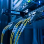
In tunnel and road monitoring systems, you typically connect pole-mounted or tunnel-mounted edge devices (cameras, LPR, traffic counters, air-quality sensors) to a centralized control room. The transport layer often uses fiber to reduce attenuation and electromagnetic interference, while SFP optics provide modularity at each switch or media converter port. A tunnel fiber SFP must handle environmental stress and maintain link stability across the full operating temperature range, while also matching the switch’s electrical and optical expectations.
Most deployments use one of two patterns: (1) an edge switch at the tunnel portal feeding a fiber ring or star topology, or (2) remote media converters bridging legacy copper to fiber and then up to the core. In both cases, the optics must align with the fiber type (single-mode vs multi-mode), the target wavelength, and the reach budget. For standards-based compatibility, verify alignment with IEEE 802.3 Ethernet PHY behavior and vendor-specific SFP implementation details. IEEE 802.3 Standard

Key tunnel fiber SFP specs that actually determine link success
Field failures usually trace back to optical mismatch or inadequate power budget, not to “bad luck.” Before buying, map your fiber plant and budget the link using module datasheet parameters (transmit power, receive sensitivity, and link penalties). Pay special attention to connector style, DOM telemetry support, and temperature rating—because tunnel enclosures can run hotter than expected when fans fail.
Spec snapshot: common SFP optics for monitoring links
Below is a practical comparison of optics you will commonly see for road monitoring backhaul. Exact values vary by vendor and part number, so treat this as a selection framework and confirm with datasheets.
| Module type | Wavelength | Typical reach | Connector | DOM | Power (typical) | Operating temp | Notes for tunnels |
|---|---|---|---|---|---|---|---|
| SFP 1G SX (MMF) | 850 nm | ~550 m over OM3/OM4 | LC | Often supported | ~1 W | -40 to +85 C | Best for short in-building or local tunnel spans |
| SFP 1G LX (SMF) | 1310 nm | ~10 km | LC | Often supported | ~1 W | -40 to +85 C | Common for portal-to-aggregation links |
| SFP 10G SR (MMF) | 850 nm | ~300 m over OM3; ~400 m over OM4 | LC | Often supported | ~2-3 W | -10 to +70 C (varies) | Use only when you have MMF plant and adequate thermal margin |
| SFP 10G LR (SMF) | 1310 nm | ~10 km | LC | Often supported | ~2-3 W | -40 to +85 C (varies) | Preferred for long SMF runs in harsh enclosures |
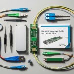
Examples of optics families you might encounter include Cisco SFP-10G-SR and Finisar/FS.com style LR/SR variants such as FTLX8571D3BCL (10G SR) and FS.com SFP-10GSR-85 (10G SR over 850 nm). Always confirm your exact SKU, reach class, and temperature range on the vendor datasheet. Cisco Product Documentation FS.com Transceivers [Source: vendor datasheets; IEEE 802.3]
Pro Tip: In road monitoring cabinets, technicians often swap optics “by wavelength only.” Instead, match the reach class and power budget to your actual fiber loss (including splices, connectors, patch cords, and aging). A module rated for 10 km can still fail on a “short” link if the plant loss is higher than assumed.
Real-world deployment scenario: portal-to-core fiber in a tunnel corridor
Consider a 3-tier road monitoring setup: 48-port 1G PoE switches at tunnel junction boxes aggregate traffic from cameras and sensors, then uplink via fiber to a corridor aggregation switch in the control building. Each junction box uses one SFP uplink at 1G LX (1310 nm) over single-mode fiber. The measured link distance from portal to aggregation is 6.2 km with 18 total splices and two patch-cord connections per end, for an estimated total loss of roughly 6.5 to 7.5 dB depending on connector type and splice quality. Choosing a tunnel fiber SFP with a conservative receive sensitivity margin (per datasheet) prevents intermittent dropouts during high humidity and cabinet temperature peaks.
In this scenario, the team also enabled DOM telemetry where available, so the NOC can alert on rising Tx laser bias or falling Rx optical power. If your switches do not support DOM readings for third-party optics, plan for operational monitoring alternatives (link-status polling, syslog alarms, or external optical monitors in critical paths).
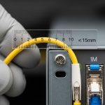
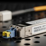
[[IMAGE:Close-up macro photography of an SFP transceiver inserted into a ruggedized industrial network switch port, with LC fiber connectors visible; shallow depth of field, cool blue tunnel lighting reflected on metal, realistic dust and condensation on the panel, high detail, 50mm lens look, photorealistic, 4k.]

Selection checklist for tunnel fiber SFP procurement
Use this ordered decision list to reduce field returns and minimize vendor lock-in risk. Engineers typically fill these items during site surveys and pre-install acceptance tests.
- Distance and fiber type: Confirm SMF vs MMF, core specs (OM3/OM4), and measured span length with splicing/connector counts.
- Wavelength and reach class: Match 850 nm to MMF and 1310 nm to SMF (or your specific design). Ensure the module reach rating covers your real loss budget.
- Switch compatibility: Verify the switch model’s supported optics list and electrical interface (SFP vs SFP+; 1G vs 10G). Some platforms are strict about optical module vendor behavior.
- DOM and monitoring needs: If you need temperature/laser bias/Rx power telemetry, confirm DOM support and how your NMS reads it.
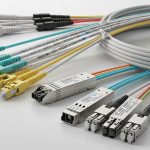
- Connector and physical fit: Most SFPs use LC; confirm bulkhead adapter types and mating hardware in the tunnel cabinet.
- Operating temperature: Prefer optics rated for the cabinet’s worst-case ambient. Tunnel enclosures can exceed expected room temperatures if ventilation is constrained.
- Vendor lock-in risk: Evaluate third-party “equivalent” optics behavior in your switch. Pilot one or two spares before scaling.
- Spare strategy: Maintain matched optics pairs for critical links and consider keeping at least one pre-tested spare per site.
Common mistakes and troubleshooting tips in the field
Troubleshooting is faster when you know the common failure modes. Below are frequent mistakes in tunnel and road monitoring deployments, with root causes and corrective actions.
Link flaps after installation despite “correct wavelength”
Root cause: Optical power budget mismatch due to underestimated splice loss or dirty connectors. High humidity can also drive connector contamination. Solution: Clean LC connectors with approved fiber cleaning tools, re-terminate if needed, and re-measure loss with an OTDR or certified loss tester. Validate Tx/Rx power using DOM if available.
No link light / PHY never comes up
Root cause: Speed mismatch (1G vs 10G optics) or switch port mode mismatch. Some switches require explicit configuration for certain transceiver types. Solution: Confirm port speed settings and transceiver speed class. Check that the SFP is the correct form factor and not an incompatible family (e.g., SFP+ expectations vs SFP).
Over-temperature shutdown or repeated reboots in hot cabinets
Root cause: Module operating temperature range is insufficient for the tunnel enclosure’s worst-case ambient, especially during fan failure or direct sunlight at portal sites. Solution: Select optics with a suitable temperature rating (commonly -40 to +85 C for robust designs), improve airflow, and log cabinet temperature. If you have DOM, monitor module temperature trends.
Works intermittently only on certain switches
Root cause: Compatibility quirks with DOM handling or vendor-specific implementation details. Solution: Test the exact transceiver model with the exact switch model before mass deployment. If third-party optics are needed, run a controlled acceptance test and track link stability metrics.
[[IMAGE:Illustrated concept art of a tunnel monitoring cabinet schematic with callouts showing an SFP module, LC fiber connectors, DOM telemetry lines, and an OTDR test point; clean vector style, dark tunnel background gradient, neon blue highlights, technical infographic feel, high readability, flat shading, no text logos.]

Cost and ROI: buying strategy for tunnel fiber SFP fleets
Pricing varies widely by speed (1G vs 10G), reach class, and temperature grade. Field teams often see OEM SFP optics priced at a premium relative to third-party equivalents; a realistic ballpark for budgeting is roughly $50 to $250 per module for common 1G SMF/MMF variants and $200 to $800+ for 10G optics depending on reach and grade. TCO should include labor for swaps, downtime risk, and the cost of spares held per site.
ROI improves when you reduce truck rolls: choose optics with the right temperature rating, confirm compatibility before scaling, and standardize on optics families that your NMS can monitor. Third-party optics can cut upfront spend, but the ROI depends on pilot results for your specific switch models and your acceptance testing process.
FAQ: tunnel fiber SFP buying decisions for road monitoring
Q1: Do I need a specific tunnel fiber SFP temperature rating?
Yes. If your cabinet can exceed standard office ambient, select optics with an industrial temperature range and validate with site thermal measurements. Prefer modules that match or exceed your worst-case ambient plus safety margin. [Source: vendor datasheets; field thermal practice]
Q2: Can I use third-party tunnel fiber SFP modules in OEM switches?
Often yes, but not always. Some switches enforce transceiver behavior or DOM handling. Run a pilot with the exact switch model, then lock the approved optic list before mass deployment.
Q3: How do I estimate optical budget for my fiber spans?
Use the module datasheet transmit power and receive sensitivity, then subtract measured fiber loss (distance-based attenuation plus splice and connector losses) from the link margin. If possible, verify with OTDR or certified loss testing.
Q4: What connector problems cause the most outages?
Dirty LC ends and poor polishing at splices/patch points are common. Clean connectors before insertion, inspect endfaces, and consider environmental sealing for tunnel cabinets to limit contamination.
Q5: Should I choose 850 nm or 1310 nm for monitoring links?
Choose based on fiber type and distance: 850 nm is typically for multi-mode short reaches, while 1310 nm is common for single-mode longer runs. Match the design wavelength to your fiber plant and reach budget.
Q6: What monitoring should I enable for tunnel fiber SFP links?
Enable DOM telemetry if your switch/NMS supports it. At minimum, monitor link status, interface errors, and power/temperature alerts where available. For critical paths, plan for periodic optical inspections.
Choosing the right tunnel fiber SFP is a site-specific engineering task: match wavelength to fiber, budget optical loss realistically, and validate switch compatibility under your environmental conditions. Next, review fiber optic transceiver compatibility to align optics, ports, and monitoring before you deploy spares across tunnel corridors.
Author bio: Field-deployed networking engineer turned market analyst, focused on fiber transport reliability and transceiver compatibility in industrial environments. I evaluate optics programs using link budgets, thermal constraints, and operational telemetry to quantify real uptime impact.