When your transport SDN fiber plan spans dozens of sites, the hardest part is rarely the spreadsheet. It is making optical transceivers, optics control, and service provisioning behave like one system. This article helps network engineers and field operations teams implement optical transceiver automation so SDN intent reliably turns into working links, with measurable checks and failure handling. Update date: 2026-04-30.
Prerequisites: what you must have before touching transport SDN fiber
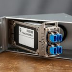
Before automation, you need a consistent hardware and telemetry baseline. In a typical deployment, you will combine a transport SDN controller with optics-capable switches or line systems, and transceivers that expose DOM data reliably. Plan for both link bring-up and optics health monitoring, since many failures show up as DOM alarms before the link fully drops.
Minimum components to stage
- SDN transport domain: a controller that can push interface state and service mapping to your transport nodes.
- Optics automation support: switches/routers or optical line systems that can read DOM and, when available, support transceiver control workflows.
- DOM-capable transceivers: SFP+/SFP28/QSFP+ or QSFP28 modules with readable temperature, bias current, laser power, and RX power.
- Telemetry path: syslog, SNMP, gNMI/RESTCONF, or vendor streaming telemetry to collect DOM and interface counters.
- Test optics and fiber map: labeled patch panels, verified polarity, and an inventory of span distances.
Target operating constraints to confirm
Ask your vendor for the exact supported optics types and DOM behavior. Also confirm temperature range and power budget for your optics class. Many “it should work” failures come from modules that are electrically compatible but do not meet the vendor’s optics profile or DOM thresholds.
Expected outcome: a staged lab or maintenance window where you can read DOM, validate thresholds, and prove SDN can request a port state change without manual intervention.
Step-by-step implementation: transport SDN fiber with optics automation
This section is a numbered implementation workflow you can run in a controlled rollout. The goal is to automate transceiver onboarding, validate optics parameters against your service profile, and bind the link to SDN transport paths.
Create an optics inventory with service profiles
Start with a structured inventory tied to service intent. For each site and each transceiver SKU, record data rate, wavelength, reach, connector, and the expected DOM thresholds. Include DOM fields you will check: temperature, laser bias current, transmit power, receive power, and any vendor-specific diagnostic flags.
Example reference parts you might see in the field: Cisco SFP-10G-SR (10G SR), Finisar FTLX8571D3BCL (10G SR-class), and FS.com SFP-10GSR-85 (10G SR, 850 nm, 300 m typical on OM3 depending on conditions). Always validate against your switch or optical system compatibility list and vendor optics policy.
Expected outcome: a “service profile” spreadsheet that SDN can map to ports, including distance-based selection rules.
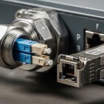
Standardize fiber mapping and polarity validation
Automation cannot fix a wrong patch. Before SDN starts toggling ports, verify fiber polarity and mapping at the patch panel. For duplex LC links, confirm Tx/Rx orientation and label both ends. For MPO links, verify polarity methodology (for example, MPO polarity adapters) and ensure the fiber ribbon mapping matches the transceiver expectations.
Expected outcome: a verified fiber map that eliminates the two dominant root causes of “no link”: swapped polarity and wrong fiber strand pair.
Deploy DOM ingestion and define pass/fail thresholds
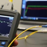
Configure your telemetry collector to ingest DOM from each optics type. Use vendor-recommended threshold ranges where available; otherwise, set conservative alarms based on observed baselines during commissioning. A practical approach is: during initial bring-up, record DOM values at stable operation, then set warning thresholds at about 1.5 to 2.0 standard deviations from the mean for temperature and optical power, and set critical thresholds closer to vendor guidance.
Expected outcome: a dashboard where each port shows current DOM values and historical trends aligned to service events.
Automate transceiver onboarding workflow in SDN transport
Implement an onboarding workflow that runs when a port is assigned to a service. The controller should: (1) set the port administrative state to down, (2) confirm DOM is readable and optics type matches the service profile, (3) validate optical power and temperature within acceptable windows, then (4) bring the interface up and confirm carrier/line protocol state.
Where the controller cannot directly “control” optics parameters, the workflow still matters: it gates service activation on DOM compliance. This turns optics from a manual check into a deterministic precondition.
Expected outcome: SDN can provision a transport SDN fiber link and either succeeds automatically or fails fast with a clear optics reason code.
Add closed-loop safeguards using interface and optical health
After provisioning, keep automation running. Trigger remediation when DOM alarms correlate with interface errors or flaps. For example, if RX power drops while temperature rises, you may have a dirty connector or a degraded patch. If bias current spikes, you may see early laser aging or a marginal optical budget.
Expected outcome: reduced mean time to repair because remediation actions start from the right signal, not just link down events.
Run a staged rollout with measurable acceptance criteria
Roll out in waves: lab, one aggregation row, one site, then full deployment. Define acceptance criteria like: 99.5% successful bring-up on first attempt, DOM read success rate above 99%, and alarm rate below your baseline. Track failure modes by category: polarity, optics mismatch, unsupported vendor policy, DOM read failure, and optical budget shortfall.
Expected outcome: a controlled rollout that produces actionable data before you scale.
Pro Tip:
In transport SDN fiber deployments, treat DOM as the “first truth” and interface link state as the “second truth.” Many optics problems show up in TX/RX power drift weeks before the link fully drops, so gating service activation on DOM compliance prevents churn and reduces ticket volume.

Optics selection: how to choose wavelengths, reach, and connectors for SDN
Selection is where most automation projects succeed or stall. Your SDN transport mapping must align with the optics physics: wavelength, reach, fiber type, and loss budget. Use IEEE 802.3 requirements for Ethernet PHY behavior, and then validate vendor datasheets for exact module characteristics and operating temperature ranges. For standards context, see [Source: IEEE 802.3].
Technical specifications comparison (representative 10G SR and 10G LR)
The table below compares common choices. Your exact module SKU may vary, but these parameters drive compatibility and service profiles.
| Parameter | 10G SR (850 nm, multimode) | 10G LR (1310 nm, single-mode) |
|---|---|---|
| Typical data rate | 10.3125 Gbps | 10.3125 Gbps |
| Wavelength | 850 nm | 1310 nm |
| Typical reach | Up to 300 m on OM3 (depends on link loss) | Up to 10 km on SMF (depends on link loss) |
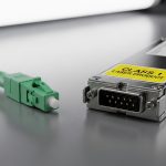
| Connector | Duplex LC (common) | Duplex LC (common) |
| Fiber type | OM3/OM4 multimode | SMF (single-mode fiber) |
| Operating temperature | Typically 0 to 70 C (varies by vendor) | Typically -5 to 70 C (varies by vendor) |
| DOM availability | Usually yes on enterprise modules | Usually yes on enterprise modules |
Decision checklist for engineers
- Distance and fiber loss: calculate worst-case link loss including patch cords, splitters, and aging margin.
- Budget and BOM policy: decide between OEM modules and third-party modules; confirm vendor acceptance rules.
- Switch compatibility: verify the exact transceiver model is supported on your switch/line system.
- DOM and telemetry support: ensure DOM fields you need are readable and stable under load.
- Operating temperature: match the module operating range to the installed environment, including airflow constraints.
- Vendor lock-in risk: evaluate whether the platform enforces strict optics policies that limit module options.
Common mistakes and troubleshooting for transport SDN fiber automation
Below are the top failure modes I see during real rollouts, with root cause and fixes. Use these as a focused troubleshooting runbook.
Failure mode 1: Port stays down despite “correct” patching
Root cause: wrong polarity or swapped Tx/Rx strands, especially after maintenance or re-cabling. This can pass visual checks but fail optical handshake. Solution: verify duplex LC polarity with a continuity tester and re-terminate or swap patch cords; for MPO, confirm polarity adapter usage.
Failure mode 2: SDN onboarding fails on optics mismatch
Root cause: the controller expects a specific optics type or DOM signature, but a different SKU is installed (even if it is electrically similar). Some platforms also enforce “vendor optics” policies. Solution: update the optics inventory mapping, confirm the module part number, and align SDN service profiles to what is actually deployed.
Failure mode 3: Link flaps after bring-up with early DOM alarms
Root cause: marginal optical budget, dirty connectors, or thermal stress leading to laser power drift. DOM may show TX power reduction or RX power degradation before carrier loss. Solution: clean connectors (proper cleaning tool and technique), measure end-to-end optical power, and check airflow/temperature; if needed, move to a higher-budget optics class or reduce span loss.
Failure mode 4: DOM read works in lab but not in production
Root cause: telemetry collector gaps, SNMP/streaming permission issues, or rate limits that drop DOM polling. Solution: validate polling intervals, confirm switch firmware compatibility, and verify telemetry transport reachability from the management plane.
Expected outcome: faster MTTR because you isolate whether the issue is fiber, optics identity, optical budget, or telemetry gating.
Cost and ROI note: what to budget for transport SDN fiber
Typical pricing varies by speed and reach, but you can estimate: OEM 10G SR modules often cost more than third-party options, while higher-speed optics (25G/40G/100G) widen the gap. For TCO, the biggest costs are not just module purchase price; they include spares inventory, truck rolls, and downtime from incorrect transceiver provisioning. A common ROI pattern: automation reduces failed bring-ups and lowers mean time to repair by using DOM-based gating and clear failure reasons, especially in multi-site deployments.
Plan spares for each optics class and connector type, and include the operational cost of cleaning supplies and verified patch cord stock. If your vendor enforces strict optics policies, OEM may be the safer route; if compatibility is broad, third-party modules can reduce capex without increasing failure rates, provided you validate DOM behavior and optics thresholds.


FAQ: transport SDN fiber and optical transceiver automation
How does transport SDN fiber automation reduce provisioning failures?
It gates service activation on transceiver DOM compliance and interface readiness instead of assuming “link up means optics are healthy.” This catches optics mismatch and marginal optical power early, before SDN marks the service as active.
Do I need DOM to implement optical onboarding?
DOM is strongly recommended because it provides temperature, laser bias current, and TX/RX power signals. Without DOM, you can still automate port state, but you lose deterministic optics validation and must rely on link events and counters.
Can I mix OEM and third-party transceivers across sites?
Sometimes, but you must verify switch or line system compatibility and optics policy behavior. The safe approach is to standardize per platform and per service profile, then validate DOM thresholds and alarm behavior during commissioning.
What telemetry interval should I use for DOM polling?
A practical starting point is collecting DOM every 10 to 30 seconds for operational visibility. For large fleets, ensure your telemetry pipeline can handle the polling rate without dropping samples, and adjust based on observed event frequency.
How do I calculate optical budget for automation decisions?
Use measured or vendor-specified link loss, then add connector and patch cord losses plus an aging margin. Automation should compare expected RX power ranges against your module’s DOM operating characteristics, not just “reach” marketing values.
What standards should I reference for Ethernet optics behavior?
IEEE 802.3 defines Ethernet PHY behavior for many transceivers and link characteristics. For optics-specific guidance, rely on vendor datasheets and platform documentation, then validate in your lab with real fiber plant conditions. anchor-text
Next step: map your service profiles to actual installed optics and fiber plant data, then roll out SDN onboarding gating in a single site first using the checklist above. For related planning, see transport SDN service mapping.
Author bio: I have deployed optics and transport SDN workflows across multi-site networks, focusing on DOM-based automation, reconciliation logic, and field troubleshooting. I write runbooks that help teams measure bring-up success and reduce truck rolls with deterministic prechecks.