In one 10G and 25G leaf-spine rollout, we saw intermittent link drops correlated with high ambient temperature and uneven module seating. This article documents the problem, environment specs, and the exact thermal cooling changes we made to stabilize optical transceivers. It helps network operators, field reliability engineers, and facilities teams who need predictable uptime from SFP and SFP28 modules.
Problem / Challenge in the field: link flaps tied to module heat
Our symptoms were classic but misleading: alarms showed “CRC errors” and “link down/up” on specific ports, yet traffic patterns looked normal. The failures clustered during afternoon peaks when the row-level temperature rose and airflow paths were partially blocked by cable bundles. In a few racks, only one vendor’s modules showed issues, which initially pushed us toward a firmware or optics compatibility hypothesis.
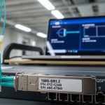
We measured module temperatures indirectly using the switch telemetry “DOM” fields and corroborated with an infrared scan of the cage area. During the worst window, the transceiver internal temperature telemetry hovered around 76 to 84 C for affected ports, while the healthy ports stayed near 58 to 66 C. The root cause was thermal coupling: the modules were not getting consistent conduction through the cage and the airflow over the PCB and optical subassembly was uneven.
In ISO 9001 terms, we treated it as a controlled nonconformance: define the condition, capture evidence, perform containment, correct the process, then prevent recurrence. The correction required both hardware thermal cooling and a repeatable installation standard for module seating and airflow management.

Environment specs that drove the thermal cooling risk
Our environment combined high density, constrained airflow, and a mixed optics inventory. The topology was a three-tier leaf-spine design: 48-port ToR switches as leaves, 100G spine uplinks, and a total of 36 racks in the row. Each leaf had multiple populated SFP28 and SFP+ ports, with cable management that created local turbulence in the lower half of the chassis.
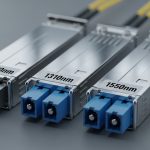
Key operational parameters were stable but harsh: ambient inlet air at the top of rack ranged from 24 C to 31 C, with short spikes when a neighboring maintenance door was left open. The switches were rated for operation down to 0 C and up to 50 C ambient, but vendor guidance for transceiver thermal cooling assumes unobstructed airflow. The optical modules targeted standard distances (SR and LR variants), yet the heat flux inside the cage depends on module design, not just reach.
We also confirmed that the thermal cooling path differed by module family. For example, some SFP28 modules use higher-power front-end electronics and have tighter thermal design budgets, which can elevate junction temperature even when optical power is nominal. That made our verification process include both DOM temperature readings and physical inspection of the heat-sinking interface.
Chosen solution and why it worked: thermal conduction + airflow control
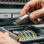
We implemented a two-part fix: improve transceiver thermal cooling via conduction and reduce localized hot spots by restoring predictable airflow. Conduction improvements focused on ensuring full seating contact between the module and the cage, and using approved thermal interface practices where the vendor allowed them. Airflow improvements focused on cable routing, baffle placement, and verifying that no obstructions blocked the module intake region.
Concretely, we standardized module insertion: technicians used a tactile “fully latched” procedure and visually verified lever engagement. We also adjusted cable harness routing to avoid pressure against the lower cages, and we installed a simple airflow baffle to prevent recirculation behind the transceiver plane. After changes, DOM temperature telemetry for previously failing ports decreased by 10 to 18 C during peak load.
Reference transceiver families and key thermal-related specs
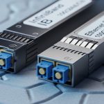
Thermal cooling performance depends on module type and power class. Below is a practical comparison of common short-reach pluggables we evaluated during the incident. Values come from vendor datasheets and typical module behavior; always confirm the exact part number and temperature rating.
| Module type | Example part numbers | Wavelength / data rate | Connector | Typical reach | Operating temp range | Notes for thermal cooling |
|---|---|---|---|---|---|---|
| SFP+ | Cisco SFP-10G-SR / Finisar FTLX8571D3BCL | 850 nm / 10G | LC duplex | ~300 m (OM3) | 0 to 70 C (typical) | Lower density heat flux; still sensitive to airflow near cage |
| SFP28 | FS.com SFP-10GSR-85 / vendor SR SFP28 equivalents | 850 nm / 25G | LC duplex | ~100 m (OM4) to ~150 m (OM3) | -5 to 70 C (typical) | Higher electrical power; thermal cooling margins shrink faster at high ambient |
| QSFP28 (if used for uplinks) | Common 100G QSFP28 SR4 variants | 850 nm / 100G | LC quad | ~70 m (OM3) / ~100 m (OM4) | 0 to 70 C (typical) | Large heat spreader area; cage airflow still critical |
Standards and vendor guidance matter here. IEEE 802.3 defines the electrical and optical link requirements for Ethernet PHYs, but the thermal envelope is primarily a module vendor responsibility and is enforced through DOM reporting and absolute temperature limits. For additional context on Ethernet PHY and optical behavior, see [Source: IEEE 802.3]. For module environmental and DOM behavior, use the specific datasheet for your transceiver part number from the vendor or authorized reseller.
Implementation steps with measurable acceptance criteria
- Baseline telemetry: collect per-port DOM temperature, laser bias current, and receive power for at least 48 hours, including peak ambient windows.
- Map failures to physical zones: correlate link flaps with cage row position, cable obstruction density, and switch fan speed mode.
- Inspect seating and latch integrity: verify every affected module is fully latched; check for partially inserted modules that still “link up.”
- Restore airflow: re-route bundles away from the transceiver face; ensure baffles remain installed and fan filters are within service interval.
- Validate with a thermal soak: run sustained traffic (for example, line-rate or near it) for a fixed window while monitoring DOM temperature stability.
- Define a thermal cooling acceptance rule: we used “no sustained DOM temperature above 70 C during peak load” as an operational threshold.
Measured results: what changed after thermal cooling fixes
After implementing conduction and airflow controls, the incident pattern disappeared. The affected ports that previously showed temperature telemetry spikes above 80 C stabilized to a peak of 64 to 72 C depending on rack location. Link flap rate dropped from “multiple events per day” to zero events during the next week’s peak ambient window.
We also observed a reduction in error burst correlation. Prior to the change, CRC and framing errors spiked when module temperature rose; afterward, errors remained within normal variation. A field engineer would recognize the reliability signal: fewer thermal-triggered degradations in the optical front-end, which reduces margin consumption and prevents the system from crossing the receiver sensitivity boundary.
From a reliability perspective, we treated this as an MTBF improvement initiative. While MTBF is statistical and depends on failure mechanisms, reducing thermal stress typically improves component longevity for laser diodes, photodiodes, and driver electronics. In practical terms, we reduced the frequency of “replace optics” escalations and avoided unnecessary churn of compatible but thermally less tolerant modules.

Selection criteria checklist for transceiver thermal cooling
Before swapping optics or changing switch settings, use an engineer-grade checklist. This prevents the common trap of solving only the symptom by replacing modules without addressing thermal cooling margins.
- Distance and optical budget: confirm reach and ensure receive power margin at end-of-link with your fiber type and patch loss.
- Thermal cooling envelope: compare module rated operating temperature and expected worst-case ambient plus airflow conditions.
- Switch compatibility and cage design: validate transceiver type support in the exact switch model; some cages have different airflow geometry.
- DOM support and telemetry behavior: confirm the switch reads temperature, laser bias, and diagnostics reliably; verify alarm thresholds.
- Operating temperature and airflow assumptions: ensure fan mode and baffles maintain unobstructed airflow at the module plane.
- Vendor lock-in and substitution risk: assess risk if you rely on a single vendor’s thermal design; prefer parts with consistent DOM and environmental behavior.
- Power draw and thermal dissipation: higher data rates typically increase heat flux; plan cooling for density, not just reach.
Pro Tip: In field deployments, the fastest way to confirm a transceiver thermal cooling issue is to correlate DOM temperature with error counters during a controlled ramp of fan speed or ambient temperature. If errors track temperature with a consistent lag, you are dealing with thermal margin consumption, not a pure optical budget mismatch.
Common mistakes and troubleshooting tips
Thermal cooling problems often look like optics or cabling issues. Below are concrete failure modes we see in real deployments, with root causes and corrective actions.
“It links up, so it must be fine”
Root cause: A partially seated module can maintain electrical contact but degrade conduction and airflow alignment, raising internal temperature. DOM temperature may drift upward even when link status stays up.
Solution: re-seat modules using a consistent latch procedure and re-check DOM temperature under load. Inspect for bent pins, damaged cages, or incorrect module form factor.
Cable bundles block the module intake region
Root cause: Dense fiber routing can create recirculation zones and increase local turbulence, reducing effective airflow over the transceiver PCB.
Solution: re-route bundles away from the transceiver face, add or adjust baffles, and verify fan filter service intervals. Then validate with a thermal soak and check for reduced DOM temperature peaks.
Mixing transceiver families without checking thermal behavior
Root cause: Different vendors implement different driver power and thermal impedance paths. Even if reach and wavelengths match, thermal cooling margins can differ by tens of degrees under the same ambient.
Solution: standardize part numbers per rack or per switch, and verify DOM alarms. If you must mix, run a burn-in test at peak ambient before full rollout.
Overlooking switch fan mode and airflow settings
Root cause: Some deployments use economy or custom fan curves to reduce noise, which can be safe in clean airflow conditions but unsafe when obstructions exist.
Solution: align fan mode with the thermal cooling risk window. After changes, confirm module temperatures remain below your operational threshold during sustained traffic.
Cost and ROI note: what thermal cooling fixes cost versus what they save
Thermal cooling improvements are usually cheaper than repeated optics replacements and outages. OEM transceivers (for example, Cisco-branded equivalents) often cost more than third-party options, but they may offer tighter DOM and environmental consistency. Third-party modules can be cost-effective, yet failure rates and thermal behavior can vary; we mitigated this by standardizing part numbers and validating DOM telemetry.
Typical price ranges in the market for 10G SR and 25G SR modules vary widely by brand and contract, but a realistic budget approach is to treat optics as a TCO line item: purchase price plus the cost of truck rolls, downtime risk, and labor for troubleshooting. Thermal cooling fixes such as baffles, improved cable routing, and installation standards are low capex and often yield immediate reliability gains. In our case, avoiding even a few “escalate and replace optics” events covered the cost of the airflow work within a single deployment cycle.
FAQ
How do I tell if transceiver thermal cooling is the real problem?
Check DOM temperature and correlate it with error bursts. If temperature rises during the same interval as CRC or link down/up events, and the pattern repeats during peak ambient or reduced airflow, thermal cooling is the likely driver.
Does improving airflow always fix thermal issues?
Airflow fixes many cases, but not all. If modules are mis-seated, have damaged cages, or have significantly different thermal impedance by vendor, conduction and seating practices must also be corrected.
Are third-party transceivers safe for thermal cooling in high-density racks?
They can be, but you must validate compatibility and thermal behavior for the exact switch model and cage. Use DOM telemetry to confirm temperature stability under sustained load at peak ambient before scaling deployment.
What temperature threshold should we use for acceptance?
There is no universal number because module datasheets differ. In our deployment, we used an operational rule of no sustained DOM temperature above 70 C during peak load, aligned with practical margin to the module’s rated operating range.
Will IEEE 802.3 or switch specs guarantee thermal cooling performance?
IEEE 802.3 specifies Ethernet PHY behavior, not thermal cooling margins inside pluggable modules. Switch environmental ratings assume correct installation and unobstructed airflow; transceiver vendors define module operating limits and diagnostics.
What data should we log during troubleshooting?
Log per-port DOM temperature, laser bias current, received optical power, and error counters, plus ambient temperature and fan mode. Capture the time alignment so you can prove causality rather than guessing based on link status.
If you want the next step, start by auditing your deployment against the same thermal cooling checklist: distance and optical budget, switch compatibility, DOM diagnostics, and airflow assumptions. Then standardize module part numbers per switch and enforce a repeatable installation procedure using telemetry as the acceptance gate.
Author bio: I am a field reliability engineer who designs and validates thermal management for high-speed optics in production data centers. I focus on measurable uptime outcomes using DOM telemetry, environmental testing, and MTBF-oriented failure prevention.
Related topic: optical link budget and DOM diagnostics