Counterfeit optical modules can turn a stable fabric into a mystery novel: link flaps, rising BER, and sudden “marginal” performance that only appears after hours in production. This guide helps network owners, data center ops, and procurement leads harden the transceiver supply chain with practical verification steps, realistic controls, and ROI math. You will get field-ready checks for DOM, vendor compatibility, and traceability without relying on luck.
Where counterfeit optics enter the transceiver supply chain

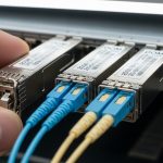
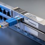
In practice, counterfeit risk clusters at three handoffs: (1) surplus and secondary marketplaces, (2) distributors that do not enforce lot-level traceability, and (3) “refurbished” inventory with unclear provenance. Optical transceivers are deceptively standardized at the mechanical level (SFP/SFP+/QSFP footprint), while electrical/optical behavior depends on laser subassemblies, driver biasing, and calibration. IEEE 802.3 defines electrical and optical performance targets, but it does not guarantee that a module claiming compliance was built and tested to the same process controls. For background on the physical layer expectations, review [Source: IEEE 802.3]. [[EXT:https://standards.ieee.org/standard/]]
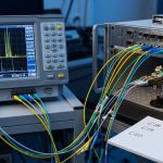
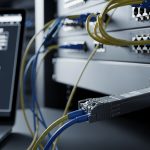
Operational tell: counterfeit modules often pass a quick “link up” test yet fail under temperature cycling, higher utilization, or strict receiver sensitivity margins. In a leaf-spine fabric, that shows up as intermittent CRC spikes and link resets when optics warm up or when fan speeds change.
Pro Tip: If your monitoring only triggers on “link down,” you will miss counterfeit behavior that manifests as rising BER before the interface ever drops. Enable optical and interface error telemetry (CRC, FEC counters where supported, and DOM threshold alarms) so you catch the slow drift.
DOM, compliance, and the hard checks that actually work
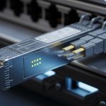
Digital Optical Monitoring (DOM) is your first line of evidence. Most modern SFP/SFP+/QSFP modules expose temperature, laser bias current, transmit power, and receive power over a management interface (commonly via I2C). Counterfeits may spoof readable values, but they frequently mismatch DOM ranges, calibration curves, or threshold behavior. Vendor datasheets for specific module families are your reference baseline; compare DOM telemetry patterns under known conditions rather than trusting static labels.
Minimum verification workflow
- Record baseline during initial burn-in: TX power (dBm), RX power (dBm), module temperature (C), and link error counters at steady load.
- Validate DOM thresholds: ensure alarm and warning thresholds match the expected behavior for the platform (switch optics monitoring profiles vary).
- Cross-check part identity: confirm the module’s vendor part number and laser/wavelength family against the switch vendor’s optics matrix.
- Stress test: run at full line rate for at least 2 to 4 hours while cycling ambient temperature if your data center has seasonal swings.
- Log and compare: if a module’s DOM “shape” differs from known-good units (not just absolute values), quarantine it.
Key specs comparison: what you must align with your switch
Counterfeit optics are often sold as “compatible,” but compatibility is not only about form factor. You must align wavelength, reach class, data rate, and connector type, and you must confirm that your switch supports that transceiver family and coding requirements. For 10G and 25G Ethernet, the electrical and optical requirements map to IEEE 802.3 PHY clauses; for practical procurement, your switch vendor’s compatibility list is the operational truth.
| Module family | Typical wavelength | Target reach | Connector | DOM support | Operating temp | Example part numbers |
|---|---|---|---|---|---|---|
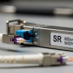
| 10G SFP+ SR | 850 nm | Up to 300 m (OM3/OM4 varies) | LC | Yes (DOM) | Commercial: 0 to 70 C; Industrial variants lower/higher | Cisco SFP-10G-SR, Finisar FTLX8571D3BCL, FS.com SFP-10GSR-85 |
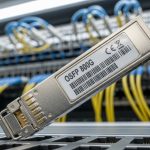
| 25G SFP28 SR | 850 nm | Up to 100 m (OM4 typical) | LC | Yes (DOM) | Commercial/extended options | Common OEM/third-party equivalents exist; verify switch matrix |
| 100G QSFP28 SR4 | 850 nm | Up to 150 m (OM4 typical) | MPO/MTP | Yes (DOM) | Commercial/extended options | Vendor-specific SR4 part numbers |
Selection implication: a counterfeit module may advertise the right wavelength and reach, but the internal laser power distribution, eye diagram quality, and receiver sensitivity margins can be off. That mismatch becomes visible as higher interface errors under realistic traffic patterns.
Selection criteria checklist for safer procurement
Use this ordered checklist before you buy. It is designed to reduce counterfeit exposure while keeping operations unblocked.
- Distance: confirm your link budget and fiber type (OM3 vs OM4), and verify reach class against your deployment distance, not marketing claims.
- Budget: set a “no surprises” price band for the exact part number and speed class; if it is far below typical, treat it as high risk.
- Switch compatibility: validate the exact module model in the switch vendor optics compatibility list; do not assume “SR means SR.”
- DOM support and behavior: ensure DOM reads expected fields and that thresholds are sensible for your platform monitoring.
- DOM support and calibration provenance: ask for lot-level documentation and test reports where available; require traceability for each shipment.
- Operating temperature: match module grade to your environment; a “commercial” module in a hot aisle can become a silent failure.
- Vendor lock-in risk: weigh OEM pricing against third-party total risk. If you use third-party optics, enforce the same verification workflow and monitoring alarms.
Common mistakes and troubleshooting signals
Even with good procurement, field realities can still trip you. Here are failure modes I have seen in deployments, with root cause and what to do next.
“Link up” success masks a marginal optical budget
Root cause: counterfeit or off-spec laser power makes the link barely pass at room temperature, then degrades as the module warms. Solution: capture DOM TX/RX at steady state and under load; compare to known-good modules and check for rising CRC/FEC-like errors.
DOM values look normal, but thresholds and alarm behavior are wrong
Root cause: spoofed DOM fields or incorrect calibration constants cause misleading telemetry. Solution: verify warning and alarm thresholds by inducing controlled temperature changes (within safe operating limits) and confirm consistent alarm behavior.
Wrong connector or fiber standard causes intermittent faults
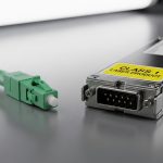
Root cause: MPO/MTP polarity issues, dirty LC ends, or OM3 vs OM4 mismatch can resemble “bad optics.” Solution: clean connectors with approved lint-free methods, inspect with a scope, then re-test; isolate by swapping a known-good module.
Compatibility mismatch with switch firmware expectations
Root cause: switch models may require specific vendor coding or module capability handling; some optics trigger conservative rate behavior. Solution: confirm switch firmware level, consult the optics matrix, and test with a validated spare.
Cost and ROI note: controlling TCO without gambling on optics
OEM transceivers often cost more upfront, but they reduce operational risk when you factor downtime, truck rolls, and incident time. Third-party modules can be economical, yet the TCO depends heavily on your verification process and failure rate. In many environments, a single outage event costs far more than the price gap between an OEM unit and a cheaper alternative; the ROI comes from fewer link flaps, faster replacements, and better prediction using DOM alarms.
Practical range: for 10G SR SFP+ optics, street pricing can vary widely by vendor and lead time; expect OEM to be higher than third-party. Your best lever is not the lowest unit price, but the lowest expected cost per “validated, monitored, and stable” module across its lifecycle.
FAQ
How do I confirm a transceiver supply chain shipment is traceable?
Request lot-level documentation: manufacturer part number, serial range, and any test reports. Then tie that to your receiving logs so each module in inventory can be audited during incidents.
What DOM fields should I monitor to detect counterfeit behavior early?
Monitor TX power, RX power, module temperature, and laser bias current. Add interface error counters (CRC and any FEC-like counters your platform exposes) and set warning thresholds before links degrade.
Can I rely on “works in my switch” compatibility claims from sellers?
No. Compatibility is model- and firmware-dependent, and optics matrices are the safer reference. Always verify the exact part number against your switch vendor list.
Is it worth buying third-party optics to reduce cost?
Often yes, if you enforce the same DOM verification and stress testing workflow. The ROI improves when you treat third-party optics as “controlled risk,” not as a blind discount.
What is the fastest troubleshooting path when a link becomes unstable?
Swap a known-good module first, then check DOM telemetry deltas and interface errors. If errors persist, inspect fiber cleanliness and connector geometry, and confirm fiber type and polarity.
Where can I verify optical and Ethernet requirements?
Use IEEE 802.3 for PHY-level targets and your switch vendor’s optics documentation for practical constraints. For general optical transceiver expectations, start with [Source: IEEE 802.3]. [[EXT:https://standards.ieee.org/standard/]]
If you want fewer surprises, treat the transceiver supply chain as a system: procurement controls, DOM-based validation, and fast incident playbooks. Next