AI training and inference are pushing data centers into higher fan-in, tighter latency targets, and faster link upgrades. This article helps network engineers and procurement teams make transceiver selection decisions for optical networking when traffic patterns change every quarter. You will compare common optics options, understand compatibility constraints, and avoid field failures that only show up under load. Updated: 2026-04-30.
AI-driven traffic changes what matters in transceiver selection
In an AI leaf-spine fabric, the “average” utilization hides bursts: microbursts from all-reduce and parameter servers can create sustained receiver power stress even when dashboards look calm. That shifts transceiver selection toward modules with stable eye diagrams, predictable thermal behavior, and strong diagnostics (DOM/MDIO/EEPROM fields). Engineers also select for upgrade paths because AI cluster sizes often jump from 64 to 256 GPUs mid-cycle, forcing port-speed changes. In practice, the best choice balances reach, power budget, and switch optics validation rather than chasing the highest headline data rate.
What AI workloads amplify
- Higher oversubscription sensitivity: congestion can trigger retransmits and link flaps that look like optics issues.
- Thermal cycling: higher port density and airflow changes raise the risk of marginal transceivers.
- Faster optics refresh: moving from 25G to 50G/100G breaks assumptions about SFP/SFP+/QSFP form factors.
- More diagnostics required: DOM alarms help isolate failing optics before they become silent packet loss.

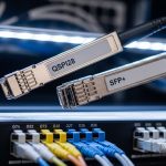
10G SFP+, 25G SFP28, 40G/100G QSFP: head-to-head performance
AI networks typically evolve from 10G to 25G and then to 50G or 100G per lane depending on switch generation and server NIC support. For transceiver selection, the key is matching the module to the switch’s electrical interface and the optical budget for your fiber plant. IEEE 802.3 defines Ethernet PHY behavior, while vendor datasheets define actual receiver sensitivity, transmit power, and supported temperature ranges. The table below compares representative modules used in real deployments.
| Option (example part) | Form factor / Data rate | Wavelength | Typical reach (OM4 / OM3) | Connector | Tx power / Rx sensitivity (typical) | Power class | Operating temperature |
|---|---|---|---|---|---|---|---|
| Cisco SFP-10G-SR (example) | SFP+ / 10G | 850 nm VCSEL | ~300 m / ~100 m | LC | Tx: about -1 to -3 dBm, Rx: about -9 to -11 dBm | ~0.8–1.2 W | 0 to 70 C (varies by vendor) |
| Finisar FTLX8571D3BCL (example) | SFP+/ 10G | 850 nm | ~300 m / ~100 m | LC | Tx and Rx within IEEE 10G-SR budget | ~0.8–1.2 W | 0 to 70 C |
| FS.com SFP-10GSR-85 (example) | SFP+/ 10G | 850 nm | ~300 m / ~100 m | LC | Tx/Rx aligned to 10G-SR | ~0.8–1.2 W | 0 to 70 C |
| QSFP28 SR module (example) | QSFP28 / 25G | 850 nm | ~100 m (varies by OM4) | LC | Tx and Rx aligned to 25G-SR | ~1.5–2.5 W | 0 to 70 C |
| QSFP28 100G-SR4 (example) | QSFP28 / 100G (4 lanes) | 850 nm | ~100–150 m (OM4 typical) | LC | Budget per lane; aggregate 100G | ~3–4.5 W | 0 to 70 C |
Why this matters for AI: 25G and 100G optics often run hotter at full utilization, and receiver sensitivity margins shrink if fiber links are aged, poorly polished, or contaminated. In addition, AI fabrics increasingly demand sub-1 microsecond path stability; transceiver-induced retraining or link resets can compound congestion. For standards grounding, engineers cross-check PHY and lane behavior against IEEE 802.3 specifications for the relevant Ethernet speeds. [Source: IEEE 802.3 Ethernet standards]
What to measure during acceptance testing
- Optical power at install: verify Tx/Rx levels against vendor thresholds using an optical power meter and the module’s DOM readings.
- Link stability under load: run traffic for at least 2 hours at target utilization and watch for CRC errors and link-down events.
- Temperature rise: confirm module case temperature stays within the vendor’s recommended operating envelope.

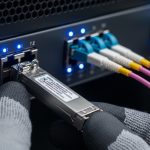
Compatibility and optics validation: the hidden cost in transceiver selection
AI deployments fail in the field more often due to compatibility than due to raw optics reach. Many enterprise and hyperscale switches implement strict verification of module EEPROM fields, supported speed modes, and vendor-specific behavior. That means your transceiver selection must include switch validation, not just datasheet match. Engineers typically rely on the vendor’s compatibility list or run a controlled lab test with the exact switch model and firmware release.
Standards and practical compatibility checks
- Form factor: SFP+, SFP28, QSFP+, QSFP28, and QSFP56 are not interchangeable electrically.
- Electrical interface: ensure the switch port expects the same lane count and signaling (for example, 4x25G for 100G-SR4).
- DOM behavior: validate that the switch reads DOM fields correctly (temperature, bias current, Tx power, Rx power, alarms).
- FEC settings: some 100G modes require or assume FEC; confirm switch configuration.
Pro Tip: In many switches, “it links up” is not the same as “it is within margin.” During acceptance, force the port into the exact speed mode you will use in production, then compare switch-reported Rx power and DOM alarms across multiple transceivers of the same batch; marginal optics often show higher variance before they show packet loss.
For authority on Ethernet PHY behavior and lane operation, consult IEEE 802.3. For module behavior and EEPROM/DOM descriptions, use vendor datasheets for the exact transceiver family you plan to buy. [Source: IEEE 802.3; vendor transceiver datasheets]

Cost and ROI: OEM vs third-party in an AI refresh cycle
In AI optical networking, transceiver selection is a supply-chain and lifecycle decision, not only a per-port purchase price. OEM optics can reduce compatibility risk, but they may carry higher unit cost and longer lead times. Third-party optics often cost less, yet can increase operational overhead if your team must manage compatibility exceptions or run more extensive acceptance testing. The ROI question becomes: what is the expected cost of downtime, RMA shipping, and delayed deployments compared to the savings?
Realistic pricing and TCO guidance
- Typical street pricing: 10G SR SFP+ modules often fall into a lower-cost range than 25G/100G QSFP optics; exact prices vary by brand, DOM capability, and lead time.
- Power and cooling: higher-speed modules consume more power; in dense AI racks, that can shift cooling requirements.
- Failure rate management: if your RMA process takes 2 to 4 weeks, the operational impact dwarfs the per-unit delta.
- Spare strategy: buy spares sized to your maintenance window and expected failure probability, not just “one extra per type.”
For reference, many engineering teams compute TCO using: unit cost + acceptance labor time + inventory carrying cost + expected RMA cost + estimated downtime cost. Use your internal incident data; if you do not have it, start with a conservative assumption and refine after the first refresh cycle. [Source: ANSI/TIA guidance on structured cabling practices impacting optical performance]
Selection criteria checklist for AI optical networking
Use the following ordered checklist when making transceiver selection decisions for AI fabrics. This sequence mirrors how field teams reduce risk: validate feasibility first, then margins, then operational fit.
- Distance and fiber type: confirm OM3 vs OM4 vs OS2, patch loss, and connector quality; compute optical budget with measured values.
- Target speed and lane mapping: match the switch port to the transceiver’s lane count (for example, 4x25G for 100G-SR4).
- Switch compatibility: check the switch vendor optics compatibility list and firmware release notes.
- DOM and monitoring: ensure the switch supports DOM fields you need for alarms and dashboards.
- Operating temperature and airflow: verify the module meets your rack ambient and airflow strategy; AI racks often run warmer.
- Budget and FEC assumptions: confirm whether FEC is required or recommended for the mode and verify configuration.
- Vendor lock-in risk: compare OEM vs third-party lead times and your ability to source alternates without revalidation.
- Spare and RMA plan: define how many spares to keep and your replacement workflow to meet maintenance windows.
Common mistakes and troubleshooting tips during transceiver selection
Even strong specs can fail in the field. Below are common failure modes engineers see when deploying optics into AI networks, with root causes and fixes.
Link comes up but errors spike under load
Root cause: optical margin is too tight due to patch loss, dirty connectors, or overly long fiber for the selected OM grade. Bias/Tx power may be within spec, but Rx sensitivity margin collapses during bursts.
Solution: clean connectors with approved procedures, re-measure end-to-end loss, and confirm DOM-reported Rx power stays above the vendor threshold across temperature. Replace the patch cords with known-good, low-loss assemblies.
Intermittent link resets after thermal ramp
Root cause: module runs near its upper temperature limit; VCSEL/receiver performance drifts and triggers link renegotiation or alarm states.
Solution: improve airflow, confirm cage/rack fan performance, and ensure the module’s operating temperature range matches the data center ambient. Validate in a burn-in test at realistic load and ambient conditions.
Works on one switch but not another
Root cause: switch port optics validation differs by model or firmware; EEPROM fields or supported speed modes do not match expectations.
Solution: use the exact compatibility list for your switch model and firmware version, or run a lab validation with the production firmware. Avoid mixing transceiver families with different DOM implementations unless validated.
Wrong connector type or polarity mistakes
Root cause: using mismatched connector assemblies (for example, LC vs MPO in the wrong context) or incorrect fiber polarity mapping in multi-fiber links.
Solution: verify connector standard, then confirm polarity using a polarity tester and the vendor’s polarity diagram. Re-terminate or re-patch using the correct polarity scheme.
Deployment scenario: AI leaf-spine with tight optics margins
In a 3-tier data center leaf-spine topology, a team deploys 48-port 25G ToR switches connecting to a spine using 100G uplinks. They standardize on 25G SR optics for server downlinks over OM4 with an engineered maximum channel loss of 2.5 dB including two connectors and one patch segment, leaving margin for aging. During the first AI training cycle, they observe CRC errors rising on a subset of uplinks after a rack airflow change; DOM shows elevated Tx bias and reduced Rx power by about 1.2 dB versus matched working ports. After cleaning and replacing patch cords, errors drop to near zero and link stability returns, confirming that transceiver selection needed to include connector and patch quality validation, not only nominal reach.
Decision matrix: match your priorities to the right transceiver selection
Use this matrix to decide between optics families and vendors. It is intentionally practical: engineers optimize for compatibility and margin, not just maximum reach.
| Priority | Best-fit choice (typical) | When it fails |
|---|---|---|
| Shortest path, highest density | 25G SR or 100G SR4 QSFP28 on OM4 with short patch lengths | Airflow too weak; module temperature drift |
| Max compatibility with minimal validation time | OEM optics from switch vendor or validated OEM-equivalent | Budget constraints or supply lead times |
| Lowest unit cost with controlled acceptance | Third-party optics with strong DOM and proven compatibility | EEPROM mismatch or DOM field differences |
| Upgrade path for AI expansion | QSFP28-based 100G options with clear lane mapping and spare strategy | Switch port speed constraints or FEC mismatch |
| Strict monitoring and alarm automation | DOM-capable modules with consistent alarm thresholds | Switch does not interpret DOM fields consistently |
Which option should you choose?
If you run hyperscale-like AI racks and need predictable installs, choose switch-validated optics (often OEM) for the first deployment wave, then consider third-party after you complete acceptance testing at your exact firmware and ambient conditions. If you are expanding gradually and want to minimize risk, prioritize compatibility and DOM monitoring over marginal reach. If budget is the primary constraint, select a third-party module only after you validate DOM alarms, optical margin with measured loss, and thermal behavior; otherwise, you may pay back savings through additional troubleshooting time. For most teams, the right transceiver selection is the one with the best demonstrated stability in your plant, not the one with the longest datasheet reach.
Next, align your cabling and patch strategy with optics performance using fiber optic cabling best practices for data centers.
FAQ
How do I start transceiver selection for an AI network if I do not know the optical budget yet?
Begin with measured fiber link loss using certified testing (end-to-end) and document connector types, patch segment counts, and expected aging. Then map each candidate module to the relevant IEEE Ethernet PHY mode and validate DOM thresholds during acceptance. If you cannot measure yet, do not rely on “typical reach” claims—optical margin is what drives stability under bursty AI traffic. [Source: ANSI/TIA structured cabling test guidance]
Are 850 nm SR optics enough for most AI data center links?
For short-reach leaf-spine and ToR-to-spine connections, 850 nm SR optics are common and cost-effective, especially on OM4. The limitation is reach margin and fiber plant quality; once loss approaches the vendor budget, errors rise sharply. For longer runs or difficult fiber plants, you may need different wavelength families or architectures.
What DOM features should I require during transceiver selection?
Require visibility into temperature, Tx bias current, Tx power, Rx power, and alarm flags that the switch can surface to your monitoring stack. Also verify how the switch interprets DOM fields and whether it supports consistent thresholds for proactive alerting. Inconsistent DOM interpretations can hide early failure signals.
Can I mix OEM and third-party optics in the same switch?
Yes in many cases, but it is not guaranteed. Compatibility depends on switch validation logic, EEPROM field expectations, and sometimes FEC or speed-mode negotiation. For a mixed fleet, run controlled acceptance tests per transceiver family and keep spares for each validated type.
Why do I see link resets only during AI training bursts?
AI training can create sustained high utilization and microbursts that stress optical margin and thermal headroom. If your connectors are marginal or fiber loss is near the budget, burst conditions expose the weakness via increased BER and link retraining. Cleaning, measured loss verification, and airflow tuning usually resolve the issue.
How many spares should we keep for transceivers?
A common approach is to base spares on your maintenance window and historical RMA/field failure rates, then add a buffer for high-criticality links. Teams often keep at least a small percentage per transceiver type plus dedicated spares for uplinks that carry the highest fan-in traffic. If your acceptance process is new, temporarily increase spares until failure patterns are understood.
Author bio: I deploy and troubleshoot optical networks in high-density data centers, validating transceivers with DOM telemetry, measured optical budgets, and load testing. I help teams translate IEEE PHY constraints and switch compatibility rules into repeatable transceiver selection and rollout plans.