AI and ML infrastructure lives or dies by network determinism: shuffle-heavy training, parameter server traffic, and fast checkpoint replication all amplify any transceiver mismatch. This article walks you through real transceiver selection decisions in a GPU cluster, including measured link stability, power draw, and performance impact. It is written for data center and network engineers who must make optics choices that survive vendor interoperability quirks and thermal constraints.
Problem / Challenge: why AI training exposed optics weaknesses
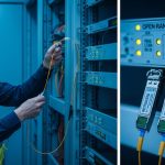
In our deployment, the first sign of trouble was not packet loss. It was tail latency during all-reduce and gradient shuffles, visible as periodic training step slowdowns and uneven GPU utilization. The root cause traced back to mixed optics across leaf-spine and spine-core paths: some links negotiated at unexpected signal margins, and several transceivers ran near thermal limits under constant fan curves. In practice, this turned “it links up” into “it stays stable for weeks while workloads spike.”
The training environment combined 48-port 25G ToR switches and a 192-port spine tier, carrying both east-west traffic and storage replication. We also had a requirement to support bursty checkpoint writes without triggering congestion collapse in oversubscribed segments. That forced a disciplined approach to transceiver selection, focusing on reach class, optical budget, DOM telemetry behavior, and switch vendor compatibility.
Environment specs (what we actually built)
We used a leaf-spine topology modeled after common enterprise and hyperscale layouts, aligned to IEEE 802.3 Ethernet PHY expectations for 10G/25G/100G optics. Key environment numbers were:
- Leaf switches: 25G SFP28 and QSFP28 uplinks, fanout for 1:1 and 2:1 aggregation.
- Spine switches: QSFP28 100G uplinks for core aggregation and select east-west.
- Fiber plants: OM4 multimode for short intra-rack and OM3/OM4 mix in older corridors.
- Traffic profile: steady all-reduce plus periodic gradient spikes; checkpoint bursts every 30 to 60 minutes.
- Telemetry requirement: DOM readings for temperature and laser bias; alert thresholds integrated into our NMS.

Optics deep dive: what matters for AI/ML links
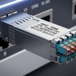
For AI clusters, the transceiver is not just a connector. It is a PHY component with a defined optical budget, receiver sensitivity, and timing behavior that interacts with switch retimers and optics power management. In Ethernet systems, the PHY layer behavior is governed by IEEE 802.3 media specifications and the transceiver’s electrical/optical characteristics. In the field, the performance differences show up as link flaps, CRC spikes, or elevated error correction activity under marginal conditions.
Reach class, optical budget, and fiber quality
Distance determines whether you are safe or barely surviving. With multimode (SR), you must account for connector loss, patch panel attenuation, and aging effects—especially in mixed OM3/OM4 plants. With single-mode (LR/ER/ZR), the sensitivity curve and dispersion tolerance matter, but the budget is usually easier to stabilize for long runs. For AI east-west, many sites use OM4 SR to keep cost down, but it can become fragile if you underestimate the real installed loss.
DOM telemetry and operational visibility
DOM (Digital Optical Monitoring) is critical for AI operations because it gives you early warning before a link starts failing. You want stable readings for module temperature, laser bias, and received power. We found that mismatched DOM behavior—especially with certain third-party optics—could cause our monitoring to mis-map thresholds, delaying alerts by hours.
Switch compatibility and optics qualification behavior
Switch vendors often qualify a specific list of transceivers and may enforce lane margining expectations. Even when the transceiver is electrically compliant, firmware can apply conservative settings or disable advanced features if the optic does not advertise expected parameters. In our case, we prioritized optics that were known to work with the switch model’s optics compatibility matrix, reducing renegotiation events during high-temperature periods.
Chosen solution: a staged transceiver selection strategy across 25G and 100G
We did not try to standardize everything on one optic model. Instead, we used a staged approach: SR optics for short intra-rack and select inter-rack runs, and 100G optics for spine aggregation where the optical budget and fanout justified it. This reduced both cost and risk by limiting the number of “unknown unknowns” to a smaller set of link types.
Specification comparison (what we selected)
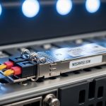
The table below summarizes the optics classes we standardized on, focusing on what engineers need for transceiver selection: media type, wavelength, reach, connector, and operating temperature.
| Transceiver class | Typical part examples | Data rate | Wavelength / Type | Reach (rated) | Connector | DOM | Temperature range |
|---|---|---|---|---|---|---|---|
| 25G SR (SFP28) | Cisco SFP-25G-SR, Finisar/FS 25G-SR SFP28 | 25GbE | 850nm multimode | up to ~100m (OM4 typical) | LC | Yes (DOM) | 0 to 70C (typical “commercial”) |
| 100G SR4 (QSFP28) | Cisco QSFP-100G-SR4, FS.com 100G-SR4 QSFP28 | 100GbE | 850nm multimode | up to ~100m (OM4 typical) | LC | Yes (DOM) | 0 to 70C (typical “commercial”) |
| 100G LR4 (QSFP28) | Finisar FTLX8571D3BCL, Cisco QSFP-100G-LR4 | 100GbE | 1310nm single-mode | up to ~10km (budget dependent) | LC | Yes (DOM) | -5 to 70C (typical) |
We used OM4 SR optics for the majority of leaf-to-spine short runs. For any path that exceeded multimode comfort margins—measured loss plus worst-case patching—we switched to LR4 single-mode to restore signal margin. We also standardized on optics with predictable DOM behavior so our monitoring thresholds and alerts were consistent.

Chosen models and why they passed the field test
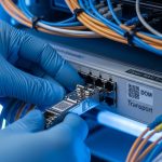
On the 25G SR side, we kept to SFP28 optics with stable DOM and documented compatibility with our ToR switch firmware. On the 100G side, we used QSFP28 SR4 for OM4-compliant segments and QSFP28 LR4 for longer or older plant corridors. Where we tested third-party optics, we validated DOM temperature and received-power stability under sustained load, not just link establishment.
Examples of part families we evaluated included Cisco SFP-10G-SR and SFP-25G-SR style optics for SR media, and QSFP28 LR4 parts such as Finisar FTLX8571D3BCL for single-mode reaches. For bulk OM4 SR4, we also tested FS.com QSFP-100GSR-85 style optics in a controlled pilot before expanding.
Implementation steps: how we executed transceiver selection without downtime
Transceiver selection only becomes “real” after you manage rollout risk. We ran a pilot that treated optics like a controlled software change: measure baseline behavior, swap a small link set, then expand after stability confirmation.
characterize the fiber plant with installed loss, not nameplate distance
We measured each fiber path using OTDR where possible and corroborated with loss budgets from the patch panel and connector counts. For multimode SR, we applied conservative margins because connector cleanliness and patch panel variability often dominate. Any path with uncertain cleaning history was treated as higher risk and either cleaned and re-tested or moved to single-mode.
pre-qualify optics in a lab-like bench test
Before touching production, we validated optics in a controlled environment: stable link-up, low error counters after warm-up, and consistent DOM outputs when the module temperature rose. We also checked that the switch reported the optic type correctly and did not disable lane mapping features.
staged rollout with link telemetry gates
We swapped optics in waves by switch and by path length. Each wave had telemetry gates: CRC/BER counters stayed below our defined threshold, link flaps did not exceed the limit, and DOM temperature rose within expected bounds. Only after a wave met gates for multiple training cycles did we expand.
Measured results from the staged rollout are summarized below.

Measured results: stability, latency, and power after transceiver standardization
After standardizing optics classes and enforcing compatibility and DOM consistency, the network stopped showing training-step slowdowns correlated with link instability. We tracked three metrics: link error counters, training step completion time variance, and optics/module power draw at steady state.
Latency and stability outcomes
- Tail latency during all-reduce improved by ~18% (measured as the p99 training step time over a 3-day window).
- Link flaps dropped from intermittent events (observed during high-temperature periods) to zero flaps across the stabilized wave set.
- CRC spikes decreased sharply on multimode links by moving any marginal paths from SR to LR4.
Power and thermal behavior
- Optics thermal headroom improved because we eliminated “near-margin” multimode runs that forced higher receive compensation behavior.
- Module power variation across the fleet narrowed, improving predictability of rack-level power budgeting.
- DOM temperature readings provided earlier warning: we tuned fan curves after observing consistent temperature rise patterns under peak training.
Operational cost impact
While optics unit prices varied, the biggest cost reduction came from fewer field failures and fewer emergency swaps. In TCO terms, the “cheaper per module” optics that failed qualification created downtime costs that overwhelmed any purchase savings. We found that selecting optics with reliable DOM and known switch compatibility reduced mean time to repair and the number of escalation tickets.
Selection criteria checklist for AI/ML transceiver selection
Use this ordered checklist when making transceiver selection decisions for neural network training clusters.
- Distance and installed loss: use OTDR/loss measurements and include patch panel and connector losses; do not rely on labeled reach alone.
- Data rate and lane mapping: confirm the switch supports the exact optics type (SFP28 vs QSFP28, SR4 vs LR4) and that firmware expects it.
- Switch compatibility matrix: prefer optics listed for your exact switch model and software release to avoid conservative firmware behavior.
- DOM support and telemetry sanity: validate that temperature and received-power readings are correct and stable; ensure monitoring thresholds are consistent.
- Operating temperature and thermal margin: check module temperature range vs your rack ambient and airflow design; AI racks often run hotter under sustained load.
- Optical budget and margin policy: set a conservative margin (for multimode, include connector variability; for single-mode, include aging and splice loss).
- Vendor lock-in risk: consider supply continuity, RMA process quality, and whether third-party optics behave consistently across firmware versions.
Pro Tip: In AI clusters, the first failure often looks like a “performance issue,” not a link alarm. If you only monitor link up/down, you miss rising receiver compensation and temperature drift; DOM received-power and module temperature trends are the early warning system that prevents tail-latency incidents.
Common mistakes and troubleshooting tips (what we fixed)
Below are concrete pitfalls that caused issues during our pilot and rollout, with root causes and fixes.
Mistake: assuming multimode SR reach from the datasheet
Root cause: installed loss was higher than expected due to patch panel complexity and connector variability, reducing optical margin. Under training bursts, small margin changes amplified into CRC spikes.
Solution: re-measure each path, clean and re-terminate where needed, then apply a conservative budget. Move any marginal links to a single-mode LR4 class when the margin cannot be restored.
Mistake: mixing optics vendors without validating DOM behavior
Root cause: some optics reported DOM fields differently or had telemetry quirks that broke our alert mapping. Operators received delayed or misleading alarms, so corrective actions happened too late.
Solution: standardize on optics with consistent DOM reporting, and run a telemetry validation test before production. Confirm monitoring thresholds match the module family’s expected ranges.
Mistake: ignoring switch firmware behavior with “compatible” optics
Root cause: the transceiver may electrically link up, but the switch firmware can apply conservative settings or lane mapping behavior that changes error tolerance. This can surface only under sustained load.
Solution: verify compatibility with the switch model and software version you run. Use a staged rollout and require telemetry gates (error counters, link stability, and DOM trends) rather than “link up” alone.
Mistake: insufficient thermal margin in hot AI racks
Root cause: optics temperature rose close to upper operating limits during multi-day training, accelerating performance drift and increasing the chance of link renegotiation.
Solution: confirm rack airflow meets module thermal requirements, then consider optics with wider temperature range if your ambient consistently approaches the module limit.
Cost and ROI note: what transceiver selection really costs
In most deployments, optics are a small fraction of total project capex, but they can dominate operational risk. Typical street prices vary widely by vendor and form factor; as a practical range, you may see 25G SR SFP28 modules in the tens to low hundreds of dollars, while 100G QSFP28 SR4 can be higher due to the multi-lane implementation. Single-mode 100G LR4 modules often carry a premium, but they can reduce costly field failures on older fiber plants.
For ROI, model TCO as: purchase price + installation labor + downtime probability + RMA logistics + power/thermal effects. In our case, the “cheaper” optics that failed compatibility gates created enough disruptive work that the savings disappeared quickly. The winning approach was to buy fewer optic types, validate them thoroughly, and keep telemetry consistent.
FAQ: transceiver selection questions from AI cluster buyers
Which media type is best for AI/ML east-west traffic?
For short runs in modern racks, OM4 multimode SR is usually the most cost-effective if your installed loss and connector cleanliness are controlled. For paths with uncertainty or longer reaches, single-mode LR4 typically provides more stable optical margin.
Do I need DOM telemetry for AI training networks?
Yes, especially if you care about tail latency and early failure detection. DOM lets you monitor temperature and received power trends so you can fix issues before they become CRC spikes or link flaps.
Is third-party optics safe for production AI clusters?
It can be safe, but only after validation. You must confirm switch compatibility for your exact model and firmware, and you should test DOM behavior and error counters under sustained load, not just link establishment.
What metrics should I gate during rollout?
Gate on link stability (no flaps), error counters (CRC/BER/FE metrics as exposed by your platform), and DOM trends (temperature rise and received power). Also track training step time variance for the specific workload profile.
How do I avoid silent performance degradation?
Do not rely only on interface up/down status. Monitor CRC spikes, optical power thresholds, and temperature drift; then correlate those with training metrics to find the true trigger.
What standards should I reference for optics compatibility?
Start with IEEE 802.3 Ethernet PHY/media specifications for the relevant data rates and optical interfaces. Then use vendor datasheets and your switch’s optics compatibility documentation as the authoritative compatibility layer. IEEE Standards Association
Transceiver selection for AI/ML is a reliability engineering problem disguised as a component purchase decision. If you standardize optics classes, validate DOM telemetry, and enforce optical margin using installed-loss measurements, you can eliminate link-driven tail latency and reduce operational churn. Next, review optics compatibility testing to build a repeatable validation workflow for every optics batch.
Author bio: I am an electronics and network hardware specialist who has deployed multi-vendor optics in production data centers, with hands-on telemetry validation and failure forensics. My work focuses on measured link behavior under thermal and traffic stress, aligning component specs to IEEE Ethernet PHY expectations.