Nothing stops a rollout like a fiber link that cannot be brought up on schedule. When optical transceivers miss their ship date, teams scramble for substitutions, temporary patching, and emergency buys that often cost more than the hardware itself. This article helps network managers and field engineers reduce transceiver lead time risk by using spec-first planning, realistic inventory math, and procurement tactics that match how vendors actually deliver. You will leave with a decision checklist, troubleshooting patterns, and a pragmatic approach to balancing OEM and third-party modules.

Why transceiver lead time stretches: the real supply chain mechanics
Extended transceiver lead time usually comes from a chain of dependencies: laser and photodiode sourcing, optical subassembly capacity, firmware and compliance test time, and distribution constraints. Even when a vendor shows “in stock,” allocations can be limited by batch testing for eye-safety, optical power, and temperature cycling. For common Ethernet optics, production uses tightly controlled processes, so lead time often spikes when demand clusters around major refresh cycles (for example, 10G to 25G migrations or new spine rollouts). The planning takeaway is simple: assume variability, then design your procurement and inventory around it.
Map lead time to what can actually fail
In practice, field teams experience lead time risk in three ways. First, the module arrives but fails switch compatibility checks (vendor-specific EEPROM behavior, DOM formatting, or signal margin). Second, the module is “compatible” but the optical budget is wrong for the installed fiber (connector loss, patch panel quality, or aging). Third, the module is correct but arrives outside the operational window, forcing a late cutover when technicians are already scheduled elsewhere.
To quantify this, ask procurement for lead time distribution, not a single number. A healthy planning model uses at least three data points: minimum, typical, and worst-case lead time, plus a failure-to-ship probability. Then you can set reorder points and staging quantities that prevent “link down” surprises.
Ground the plan in standards and operating envelopes
Most Ethernet optics align to IEEE 802.3 physical layer requirements, while optical performance and safety depend on vendor datasheets and test reports. For example, 10G SR optics are typically specified for multimode fiber operation, while 25G SR and 100G variants depend on their lane rates and modulation. Your planning must also respect operating temperature ranges; many transceivers specify a 0 to 70 C commercial range or -40 to 85 C extended range, and the wrong temperature class can reduce reliability.
For authoritative baseline requirements, use IEEE 802.3 for electrical and optical interfaces and vendor datasheets for exact parameters. For standards and electrical/optical alignment, see Source: IEEE Standards. For practical compatibility and module behavior, also review vendor technical notes for DOM and EEPROM formats, typically documented in datasheets.
Pro Tip: Field experience shows that “DOM supported” is not binary. Some switches accept the module’s presence and reach the link, but still misread thresholds or alarms if the DOM implementation differs from what the switch expects. During a pilot, validate DOM readouts (temperature, bias current, TX power, RX power) for at least 24 hours under normal traffic before you scale procurement.
Specs that decide reach, compatibility, and delivery urgency
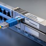
When transceiver lead time becomes a constraint, teams often rush to “any module that fits.” That approach backfires because the right form factor can still fail on wavelength, fiber type, or optical power. The fastest way to reduce risk is to lock down the required parameters before you contact suppliers: wavelength, data rate, reach class, connector type, fiber grade (OM3/OM4/OM5), and whether your environment requires extended temperature operation.
Quick comparison: common Ethernet optics you will actually buy
The table below compares representative modules frequently used in enterprise and data center networks. Exact values vary by vendor and speed grade, but these categories reflect typical planning ranges. Always confirm the specific module part number against the switch vendor compatibility list and the installed fiber plant.
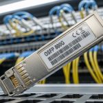
| Module type | Data rate | Wavelength | Typical reach (MMF/SMF) | Connector | Power class | Operating temp | Example part numbers |
|---|---|---|---|---|---|---|---|
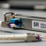
| SFP+ SR | 10G | 850 nm | Up to 300 m on OM3 / up to 400 m on OM4 | LC | ~0.8 to 1.5 W (varies) | 0 to 70 C or -40 to 85 C | Cisco SFP-10G-SR, Finisar FTLX8571D3BCL, FS.com SFP-10GSR-85 |
| SFP28 SR | 25G | 850 nm | Up to 100 m on OM3 / up to 150 m on OM4 (typical planning) | LC | ~1.5 to 2.5 W (varies) | 0 to 70 C or -40 to 85 C | Vendor-specific 25G-SR modules for SFP28 |
| QSFP28 SR | 100G (4x25G) | 850 nm | Up to 100 m on OM4 (typical) | MPO/MTP | ~3 to 6 W (varies) | 0 to 70 C or -40 to 85 C | 100G-SR4 QSFP28 examples vary widely by vendor |
| QSFP28 LR | 100G (4x25G) | 1310 nm | Up to 10 km on SMF (typical planning) | LC | ~3 to 6 W (varies) | 0 to 70 C or -40 to 85 C | 100G-LR4 QSFP28 examples vary by vendor |
Even within the same category, vendors differ in optical power, receiver sensitivity, and how they handle temperature drift. During transceiver lead time planning, treat the module as a performance object, not just a SKU. Require the supplier to provide the datasheet values you need for your optical budget calculation, including worst-case TX power and receiver sensitivity.
DOM, EEPROM, and switch behavior: compatibility is a spec too
Many switches rely on DOM data and thresholds to trigger alarms and support monitoring. DOM implementations follow common practices, but interoperability can vary. Before committing to a second vendor, test that the switch reads DOM values correctly and that alarms (high/low thresholds) behave as expected under your temperature and traffic profile.

Planning strategies to prevent last-minute optics shortages
Extended transceiver lead time is manageable if you treat optics procurement like a reliability program. The goal is to avoid both stockouts and waste. Your strategy should align with cutover dates, fiber readiness, and the probability of link failures during staging.
Use a reorder point model tied to cutover dates
Start with a forecast: how many ports will be activated between Week 0 and Week N. Then add safety stock based on the worst-case lead time and your receiving turnaround. A practical method is:
- Compute demand during lead time: Daily activation rate × lead time days.
- Add safety stock: target coverage for the 80th to 95th percentile lead time, plus a small buffer for DOA or compatibility testing returns.
- Stage modules before field work: aim to have optics on-site at least 2 to 3 weeks before the first cutover window when possible.
Dual-source with controlled equivalency
Instead of “any vendor,” define equivalency rules. For example: same speed grade, same interface standard, same connector type, same optical reach class, and matching DOM support expectations. Then create a shortlist of two or three approved part numbers per link type. When lead time stretches, you can switch sources without re-verifying every parameter from scratch.
Pre-qualify substitutes and lock compatibility early
Field reality: you will not have time to qualify modules during a live outage. So run a qualification sprint before the bulk order. Validate link bring-up, error counters, DOM reading, and optical power levels. If your switch vendor provides compatibility lists or transceiver validation guidance, use them as a starting point, then still test in your specific environment.
Deployment scenario: how lead time planning saves a leaf-spine rollout
Consider a 3-tier data center leaf-spine topology with 48-port 10G ToR switches in the access layer and 40G spine uplinks aggregated through a staged migration to 25G. In one rollout window, the team planned to activate 96 access uplinks and 24 spine uplink groups over two weekends. The original transceiver order used a single vendor with a quoted lead time of 5 weeks; however, during the procurement cycle the vendor’s worst-case lead time slipped to 9 weeks due to optical subassembly constraints.
Because the team had built a safety stock model, they had staged 30% of the required optics on-site 3 weeks early for compatibility testing and staged patching. During bring-up, two modules showed DOM misreads on thresholds, but the links still came up; the team replaced those units using the pre-qualified second source without delaying the cutover. Result: the rollout completed on schedule, and the “emergency buy” risk cost was avoided. The operational lesson is that transceiver lead time mitigation is not only about shipping; it is about having tested alternatives ready.

Common mistakes and troubleshooting patterns when optics arrive late
Even with good planning, optics can fail. These are the most common transceiver lead time-related mistakes I have seen in the field, along with root causes and fixes.
Buying the right connector but the wrong fiber grade
Failure mode: Link flaps or never comes up; link negotiation may fail or stay at low error tolerance. Root cause: Multimode reach assumptions do not match installed fiber (for example, OM3 versus OM4), plus patch panel and connector losses exceed budget. Solution: Recalculate the optical budget using measured fiber attenuation and worst-case connector loss. Confirm the module reach class and ensure you use the correct fiber type (and clean connectors).
Assuming “compatible” means “DOM alarm behavior will match”
Failure mode: Switch logs show DOM threshold alarms, or monitoring dashboards show null values; sometimes maintenance tickets escalate unnecessarily. Root cause: DOM implementation differences: EEPROM field mapping, threshold scaling, or sensor read cadence. Solution: During qualification, verify DOM reads and alarm thresholds for your switch model; if needed, configure monitoring to use raw values or adjust thresholds based on vendor datasheet guidance.
Ignoring temperature class and operating envelope
Failure mode: Works during bench test but degrades in an enclosed rack with higher ambient temperature; error counters increase over time. Root cause: Temperature outside the module’s specified operating range, or airflow differences compared with test conditions. Solution: Confirm rack ambient temperature distribution and compare to the module’s operating temperature range (commercial 0 to 70 C vs extended -40 to 85 C). Add thermal verification during staging.
Cleaning and handling shortcuts after “emergency” delivery
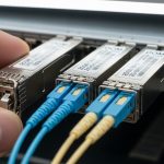
Failure mode: Intermittent loss of signal after installation; high bit error rate despite correct specs. Root cause: Dirty LC/MPO endfaces from handling, shipping dust caps not removed correctly, or MPO polarity mismatch. Solution: Use approved fiber cleaning tools, inspect with a scope, verify MPO polarity mapping, and test with known-good patch cords.
Cost and ROI: balancing OEM, third-party, and inventory carrying risk
When transceiver lead time stretches, cost comparisons can become misleading. OEM optics are often priced higher but may reduce compatibility friction and returns. Third-party modules can reduce unit cost, but you must budget for qualification time, compatibility testing, and a slightly higher probability of needing exchanges.
Typical street pricing varies by speed, reach, and vendor, but as a planning baseline: 10G SR SFP+ modules often cost roughly in the low tens of dollars to a higher tier depending on brand and temperature class; 25G SR SFP28 modules can be higher; 100G optics often cost substantially more. Total cost of ownership (TCO) includes inventory carrying costs, storage risk, and the operational cost of delays. If your rollout date is tied to revenue, the ROI of stocking tested alternatives early can dwarf the unit price difference.
If you can, negotiate with suppliers for flexible allocation, partial shipments, and documented lead time distributions. The cheapest unit with the longest delay can be the most expensive line item once you account for downtime and rework.
FAQ
How do I plan for transceiver lead time when vendors quote only a single number?
Ask for a lead time distribution: minimum, typical, and worst-case, plus any allocation limits. Then model safety stock for the 80th to 95th percentile worst case, and stage modules before cutover by 2 to 3 weeks when possible.
Can I use third-party optics to reduce transceiver lead time without risking downtime?
Yes, if you use controlled equivalency rules and pre-qualify part numbers in your switch environment. Validate link bring-up, DOM behavior, and optical power margins before scaling beyond a pilot batch.
What data do I need for an optical budget to avoid late-arrival surprises?
Use measured fiber attenuation, connector and splice loss assumptions, patch panel quality, and worst-case TX/RX power from the module datasheet. Then confirm that the reach class matches your installed fiber grade and that polarity and cleaning practices are correct.
Why do links come up but monitoring shows DOM errors?
DOM implementations can differ in how thresholds, scaling, and sensor fields map into switch monitoring expectations. During qualification, verify DOM reads over time and adjust monitoring or thresholds if your switch supports that configuration.
What is the fastest troubleshooting path when an optical module arrives late and the link fails?
First verify physical layer basics: correct port type, correct fiber type, connector cleaning, and MPO polarity. Next confirm the module part number, DOM compatibility expectations, and optical budget against measured losses, then check switch logs and error counters for pattern clues.
Do I need to worry about operating temperature when planning transceiver lead time?
Absolutely. A module that works in a bench test can drift or degrade if installed ambient temperature exceeds its specified operating range. Compare rack ambient conditions to the module temperature class and validate airflow during staging.
If you want to turn this into a repeatable program, start by standardizing your approved optics list and running a quarterly qualification refresh before lead time spikes. Next, build a procurement playbook that includes dual-source equivalency, safety stock math, and DOM validation for each switch model: how to plan an optics inventory.
Author bio: I have deployed and troubleshot Ethernet optics in live data center cutovers, including DOM and optical budget validation under tight maintenance windows. I write with field-tested procurement and engineering practices to help teams protect uptime when transceiver lead time becomes unpredictable.