When an optical link drops or flaps, the first suspect is often the transceiver. This article helps network and field engineers perform transceiver failure troubleshooting with repeatable checks: DOM readings, optical power, connector inspection, and switch compatibility. You will also learn common failure modes that mimic “bad optics,” plus practical recovery steps for live data center and enterprise fiber runs.
What “transceiver failure” really means in fiber networks
In practice, transceiver failures present as link loss, CRC errors, FEC uncorrectable events, or high BER that never fully recovers. The physical layer can fail due to optical power issues, laser bias problems, receiver sensitivity degradation, or firmware incompatibility. IEEE 802.3 defines key electrical and optical behaviors for Ethernet PHYs, while vendors add implementation details such as Digital Optical Monitoring (DOM) thresholds and alarm masks.
Start by classifying the symptom: is the link down, up but errors, or intermittent? Then map it to likely causes: optics/laser, fiber path loss, connector contamination, polarity mismatch, or switch-side configuration. If you can, capture timestamps and interface counters before you swap anything; this speeds root-cause analysis.
Key optical and interface signals to capture first
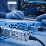
On the switch, record: interface admin state, link state, negotiated speed, FEC mode, and counter deltas (CRC, symbol errors, FEC corrected/uncorrectable). On the transceiver, read DOM values such as Tx bias current, Tx power, Rx power, laser temperature, and alarm/warning flags. Many failures show patterns: for example, Rx power too low with stable Tx power usually points to fiber loss or contamination.
For standards context, consult IEEE 802.3 relevant clauses for your PHY family, and vendor datasheets for the transceiver’s supported DOM and diagnostic page fields. For DOM and optical monitoring background, see IEEE 802.3 overview and vendor platform documentation via your switch manufacturer support portal.

Measurement-driven troubleshooting workflow for optical modules
A reliable transceiver failure troubleshooting workflow reduces guesswork. Use a “measure, isolate, verify” approach: measure DOM and counters, isolate the optics from the fiber, verify polarity and cleaning, then validate link behavior after each change. This minimizes downtime and avoids unnecessary swaps that can hide the real root cause.
Verify compatibility and DOM visibility
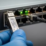
Some platforms require vendor-approved transceivers or enforce compatibility checks. Confirm the module type (SFP/SFP+/QSFP/QSFP28/CFP2) matches the switch port speed and breakout mode. If DOM is partially visible or alarms are inconsistent, check whether the transceiver supports the switch’s diagnostics interface expectations (often via I2C management and standardized diagnostic registers).
Compare DOM readings against thresholds
DOM values vary by manufacturer and temperature, but trends matter. If Tx power is near the low end while bias current is high, the laser may be aging or failing. If Rx power is extremely low while Tx output appears normal, suspect fiber attenuation, connector contamination, or wrong wavelength pairing (for example, mixing SM and MM optics).
Validate optical path loss with a power meter
When possible, use an optical power meter and reference launch conditions to quantify link budget. For multimode links, verify you are using the correct fiber type and launch method (e.g., OM3/OM4 with 850 nm VCSEL). For single-mode 1310/1550 nm links, verify fiber is clean and that attenuation is consistent with the expected route length and splices.
Inspect and clean connectors using proper tools
Connector contamination is one of the most frequent “looks like a bad transceiver” issues. Use a fiber inspection scope and clean with validated procedures (dry cleaning tools or appropriate solvent methods per your site policy). Re-test after cleaning before declaring the module defective.
| Transceiver example | Wavelength | Typical reach (per spec) | Connector | Data rate | DOM support | Operating temperature |
|---|---|---|---|---|---|---|
| Cisco SFP-10G-SR | 850 nm | Up to 300 m (OM3) / 400 m (OM4, typical) | LC | 10G (SFP+) | Vendor DOM | 0 to 70 C (varies by SKU) |
| Finisar FTLX8571D3BCL | 850 nm | Up to 300 m (OM3) / 400 m (OM4, typical) | LC | 10G (SFP+) | Digital diagnostics | 0 to 70 C |
| FS.com SFP-10GSR-85 | 850 nm | Up to 300 m (OM3) / 400 m (OM4, typical) | LC | 10G (SFP+) | DOM (vendor format) | -40 to 85 C (varies by product line) |
Pro Tip: If Tx bias current is abnormally high but Tx power is low, treat it as a likely laser health issue and swap the module first. If Tx power is normal yet Rx power is low, prioritize fiber cleaning and polarity verification before replacing optics, because contamination can attenuate far more than aging would at first.

Common mistakes in transceiver failure troubleshooting
Even experienced teams can misdiagnose optical problems, especially when counters lag or when multiple issues coexist. Below are concrete failure modes and the fastest corrective actions.
Pitfall 1: Assuming “link down” means “bad transceiver”
Root cause: Port speed mismatch, breakout mode misconfiguration, or inconsistent FEC settings can keep the PHY from training. Some platforms also shut down ports when they detect unacceptable DOM alarms.
Solution: Confirm port configuration (speed, breakout, FEC mode) and compare with the intended transceiver type. Re-seat the module and verify DOM alarms clear after a short stabilization window.
Pitfall 2: Skipping connector inspection and cleaning
Root cause: Dust on LC end-faces can cause rapid attenuation and intermittent link flaps that look identical to receiver degradation. This is especially common after maintenance or patch cord rework.
Solution: Inspect with a fiber scope, clean with approved tools, then re-test DOM and link counters. If you have spare jumpers, test using a known-clean patch cord to isolate the problem quickly.
Pitfall 3: Mixing polarity or mismatching transmit/receive pairs
Root cause: In duplex LC cabling, swapping fibers (Tx to Rx) can produce very low Rx power and high error rates, sometimes with link training failures. This often occurs during rack moves or patch panel re-termination.
Solution: Verify polarity end-to-end using a polarity tester or by tracing patch cords to the correct transceiver lanes. Re-terminate or use polarity-correct patch leads if your system expects A-to-A and B-to-B mapping.
Pitfall 4: Ignoring temperature and aging trends
Root cause: A module that works at room temperature may fail in a warmer patch bay due to laser temperature drift and reduced margin. DOM warnings can be subtle until the link is already unstable.
Solution: Compare DOM across time and across ports. If temperature is near the vendor’s upper limit, improve airflow and validate module selection for the site’s thermal envelope.

Deployment scenario: recovering a flapping 10G OM4 link
In a 3-tier data center leaf-spine topology, a team observed flapping on a 10G uplink between a top-of-rack switch and a distribution router. The affected fiber run was approximately 85 m on OM4, using LC duplex patch cords. DOM on the SFP+ showed Rx power dropping from about -6 dBm to below -18 dBm during incidents, while Tx power remained relatively stable around the expected range.
The team first verified port configuration and confirmed the switch negotiated 10G with the intended optics profile. They then inspected the LC connector ends and found visible contamination; after cleaning and re-testing, Rx power returned to -7 to -9 dBm and the link stabilized for the next 72 hours. A later audit confirmed that the patch cords had been handled during adjacent maintenance, explaining the intermittent nature.
Selection criteria checklist to avoid repeat failures
Use this ordered checklist when selecting or replacing optical transceivers to reduce future transceiver failure troubleshooting effort.
- Distance and fiber type: confirm OM3 vs OM4 vs single-mode and verify wavelength (850 nm vs 1310/1550 nm).
- Budget and connector loss: include patch cords, couplers, splices, and expected worst-case attenuation.
- Switch compatibility: validate supported transceiver lists and port speed modes; confirm DOM behavior.
- DOM and alarm thresholds: ensure the module exposes diagnostics in a way your platform interprets correctly.
- Operating temperature: match the transceiver temperature range to your enclosure and airflow conditions.
- Vendor lock-in risk: consider OEM vs third-party tradeoffs; require return/RMA terms and performance characterization.
- Spare strategy: keep known-good modules and jumpers to isolate faults quickly during outages.
Cost and ROI considerations for transceiver replacements
Typical pricing varies by speed and vendor, but for 10G SFP+ SR optics, field experience often places third-party modules in the range of $40 to $120 each, while OEM-branded modules can be higher (commonly $80 to $250 depending on channel and warranty). The real ROI comes from reducing downtime and avoiding repeated truck rolls: a $60 module is expensive if it masks a $2 cleaning issue that would have resolved the link.
TCO should include power draw (usually a few watts per module, depending on technology), expected failure rates under your thermal conditions, and RMA handling time. For high-availability sites, prioritize transceivers with strong documentation, consistent DOM readings, and clear warranty terms over lowest unit cost.
FAQ
How can I tell if a transceiver is failing versus the fiber?
Check DOM trends: if Tx power is low while bias current is high, laser health is suspect. If Tx power is normal but Rx power is low or fluctuates, focus on fiber loss, connector contamination, and polarity.
What DOM values are most useful for transceiver failure troubleshooting?
Tx bias current, Tx optical power, Rx optical power, and temperature are the most actionable. Also review warning/alarm flags and confirm whether the switch reports DOM consistently after link training.
Do third-party optics always work in enterprise switches?
Not always. Some platforms enforce compatibility profiles or react differently to DOM alarm thresholds. Verify support using the switch vendor’s documented optics list and test in a maintenance window before scaling.
Why does a link flap after cleaning but later fail again?
Common causes include incomplete cleaning, re-contamination from handling, or a damaged fiber end-face. If the scope shows scratches or cracks, replace the patch cord and re