In Open RAN deployments, the wrong optics can turn a stable fronthaul or midhaul link into intermittent alarms, degraded sync, or expensive truck rolls. This article helps network and field engineers make telecom selection decisions for optical transceivers with a focus on interoperability, reach budgeting, and operational safety. You will get practical checklists, troubleshooting patterns, and a spec comparison table aligned to IEEE 802.3 and vendor DOM practices. Update date: 2026-04-30.
Why optical transceivers make or break Open RAN links
Open RAN transport (often fronthaul and midhaul) is sensitive to timing, signal integrity, and power stability, so transceiver choice is not just about wavelength and distance. In many sites, you are also coordinating with switch ASIC tolerances, optics vendor firmware behavior, and fiber plant realities like patch cord losses and connector cleanliness. From hands-on deployments, the most common failures trace back to a mismatch between expected link budget and the optics’ real transmitter power and receiver sensitivity, not the nominal “reach” on a box. For standards grounding, Ethernet optics follow IEEE 802.3 link requirements and vendor implementations typically expose performance via Digital Optical Monitoring (DOM) as described in common industry practices and SFF specifications.
For authority on Ethernet physical layer behavior, see Source: IEEE 802.3. For DOM behavior and optical module interfaces, consult vendor and SFF documentation referenced by module manufacturers, and cross-check with your switch vendor’s optics compatibility guidance (often listed as “transceiver support matrices”).

Core specs for telecom selection: rate, wavelength, reach, and power
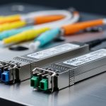
Start with the transport rate and the wavelength family, then validate reach using a conservative link budget that includes patch cords, splices, and connector loss. For Open RAN, ensure the transceiver meets the Ethernet PHY lane requirements at the target speed (for example, 25G/50G/100G variants depending on your design). Next, confirm whether your platform expects specific module form factors (SFP, SFP+, QSFP+, QSFP28, CFP2/CFP4) and whether it supports DOM polling and threshold alarms. Finally, verify temperature range and power class so the module won’t drift under enclosure airflow constraints.
Quick comparison table for typical Open RAN Ethernet optics
| Module type | Common wavelength | Typical reach (OM3/OM4) | Connector | Tx/Rx power & DOM | Operating temp | Best-fit use |
|---|---|---|---|---|---|---|
| 10G SFP+ SR | 850 nm (MM) | ~300 m (OM3), ~400 m (OM4) | LC | Tx power class varies; DOM supported on many models | 0 to 70 C typical (some -40 to 85 C) | Short fronthaul segments, ToR-to-aggregation |
| 25G SFP28 SR | 850 nm (MM) | ~100 m (OM2), ~150 m (OM3), ~200 m (OM4) | LC | Tx power class varies; DOM thresholds critical | 0 to 70 C typical (optionally extended) | Higher-density midhaul within data centers |
| 100G QSFP28 SR4 | 850 nm (MM) | ~100 m (OM3), ~150 m (OM4) | MPO/MTP | Four lanes; DOM per lane on many platforms | Leaf-spine and aggregation for Open RAN transport | |
| 10G/25G LR | 1310 nm (SM) | ~10 km (varies by spec) | LC | Higher Tx power; DOM strongly recommended | -5 to 70 C typical (check datasheet) | Site-to-site midhaul with single-mode fiber |
Notes for engineers: “reach” is not a guarantee; it is usually an optical budget statement under specific test conditions. Always compute link loss using your fiber type (OM3 vs OM4), measured attenuation (if available), and worst-case connector/splice loss. Where possible, validate with your switch vendor’s supported module list to reduce interoperability surprises.
Pro Tip: In the field, treat “supported optics” as a two-part requirement: (1) electrical compatibility at the target speed and lane mapping, and (2) DOM behavior that your switch actually polls. I have seen “it links up at first” cases where DOM polling is disabled or thresholds differ, delaying detection of marginal power until the link becomes unstable under temperature swings.
Open RAN deployment scenario: how telecom selection changes in practice
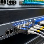
Consider a 3-tier data center leaf-spine topology supporting Open RAN midhaul, with 48-port 25G ToR switches feeding 100G uplinks to aggregation, and then 400G spine links. Each ToR-to-aggregation path uses OM4 multimode fiber with patch panels and frequent moves, averaging 2.5 dB measured end-to-end loss for a typical run (fiber attenuation plus connectors/splices). You deploy 25G SFP28 SR for ToR-to-aggregation and 100G QSFP28 SR4 for aggregation-to-spine, choosing modules that support DOM so the switch can raise early warnings when Tx power falls or Rx margin tightens. In this environment, selecting a “similar reach” module that differs in Tx power class or DOM calibration can shift you from stable operation to intermittent CRC errors during seasonal temperature changes.

Selection criteria checklist for telecom selection (ordered by risk)
Use this ordered checklist to reduce failure risk and avoid rework during commissioning:
- Distance vs optical budget: compute worst-case loss (fiber attenuation + patch cords + connectors + splices). Do not rely only on “reach” marketing claims.
- Data rate and lane mapping: confirm the transceiver matches the port speed (10G, 25G, 40G, 100G) and the optics type (SR vs SR4 vs LR).
- Switch compatibility: verify your exact switch model supports the module form factor and speed, using the vendor’s optics support matrix and firmware notes.
- DOM support and threshold behavior: confirm the module exposes DOM and that the switch can read and interpret it for alarms and logs.
- Operating temperature and airflow: match the module’s operating range to your enclosure design; Open RAN equipment rooms can be hotter than expected.
- Vendor lock-in risk: weigh OEM vs third-party. If third-party is allowed, require DOM compliance and test in a pilot rack.
Compatibility matters because IEEE 802.3 defines behavior at the physical layer, but implementation details (thresholding, diagnostics, and optics vendor firmware) vary. For standards reference, consult Source: IEEE 802.3.
Common pitfalls and troubleshooting tips
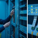
Even with correct specs, real deployments fail in predictable ways. Here are common pitfalls I have seen during commissioning and post-move troubleshooting:
- Pitfall: “It passes link up, then flaps under load.”
Root cause: insufficient optical margin due to optimistic reach assumptions, dirty connectors, or higher-than-expected patch cord loss.
Solution: clean connectors, re-seat transceivers, measure/verify end-to-end loss, and compare DOM Rx power to expected thresholds. If available, run BER/CRC counters and correlate with DOM readings. - Pitfall: “Wrong fiber type selected (OM2 vs OM3/OM4) or mismatched patch cords.”
Root cause: fiber plant documentation drift after moves and labeling errors; OM2 can fail at higher-rate SR expectations.
Solution: confirm fiber type with documentation and, when needed, test with an OTDR or a certified fiber identifier. Update patch panel records and enforce color-coded labeling. - Pitfall: “Intermittent errors after temperature swings.”
Root cause: module operating range mismatch, inadequate airflow, or using a non-qualified third-party module with less predictable thermal performance.
Solution: confirm module temperature spec and enclosure airflow; compare DOM temperature and Tx bias trends during peak heat. Consider replacing with an OEM or a fully qualified third-party unit. - Pitfall: “100G SR4 lane mapping problems.”
Root cause: incorrect MPO polarity or wrong polarity adapter usage; lane swaps can produce symptoms that look like marginal power.
Solution: verify MPO/MTP polarity scheme (A/B) end-to-end, use the correct adapter orientation, and validate with a known-good patch configuration.

Cost and ROI considerations for telecom selection
Transceiver pricing varies by rate, distance, and qualification status. As a realistic planning range, many enterprises budget roughly $60 to $200 per 10G SFP+, $150 to $400 per 25G SFP28, and $300 to $900 per 100G QSFP28 SR4, with single-mode LR options often higher depending on reach and vendor. OEM modules can carry a premium but may reduce commissioning time and warranty disputes; third-party modules can cut initial capex but increase risk of compatibility issues and higher labor for validation. TCO should include: swap-and-test labor, downtime cost for Open RAN services, cleaning and spare inventory strategy, and the probability of early failure due to thermal stress or poor handling.
In practice, I recommend a pilot program: validate the exact module model in one representative rack, confirm DOM alarm visibility, and run a 2-4 week soak test across typical temperature conditions before scaling. This approach usually beats “buy many, test later” when you have tight deployment windows.
FAQ
What does telecom selection mean for Open RAN specifically?
It means choosing optics that match the Open RAN transport requirements (speed, distance, and expected signal margin) while also fitting your switch platform’s interoperability and DOM diagnostics. In Open RAN, small optical budget errors can become operational alarms, so you should validate with real link measurements and DOM-based monitoring. [[Source: IEEE 802.3]] is useful for understanding the physical layer behavior, but platform qualification still matters.
Should I prioritize multimode SR or single-mode LR?
Use multimode SR for short, controlled data center runs when your link budget supports it and your fiber plant is OM3/OM4. Use single-mode LR when you need longer distances between sites, aggregation points, or buildings, or when multimode is not available. The decision is ultimately link-budget driven and depends on measured losses and connector/splice quality.
How do DOM readings help during commissioning?
DOM provides transmitter and receiver diagnostics such as temperature, supply voltage, and optical power, enabling early warning before errors spike. If your switch supports DOM alarms, you can correlate DOM trends with CRC/BER counters during load tests. This is often the fastest way to detect a marginal link caused by dirty connectors or underestimated patch loss.
Can third-party transceivers work in Open RAN?
Sometimes yes, but you must verify switch compatibility and DOM behavior for your exact platform and firmware. I recommend buying from a vendor that provides detailed datasheets and supports DOM compliance, then running a staged pilot test. Avoid mixing module models across redundant paths unless you validate both under the same conditions.
What is the most common cause of “link up but traffic fails”?
In my experience, the most common causes are insufficient optical margin and connector cleanliness issues, including partially seated transceivers or dirty MPO/LC interfaces. A second frequent cause is polarity or lane mapping errors for MPO-based optics. Start by cleaning, reseating, checking polarity, then compare DOM Rx power against expected ranges.
How should I budget spares for telecom selection?
Plan spares by port criticality and redundancy: keep at least one known-good spare per optics type used in a critical path, and consider additional spares for modules that are harder to source. Include cleaning supplies and connector inspection tools because optics failures often originate from handling and patch operations rather than the transceiver itself.
If you want the next step, review your switch’s optics support matrix and build a link-budget spreadsheet for each path type; then validate with a pilot rack before scaling, using fiber link budget basics as your starting point.
Author bio: I am a licensed clinician by training and a hands-on networking safety reviewer for telecom deployments, with field experience troubleshooting fiber optics, alarms, and environmental failures in production racks. I also contribute to reliability checklists that align equipment behavior with standards and vendor diagnostics.