Open RAN rollouts fail for mundane reasons: a mismatched optics budget, a DOM compatibility glitch, or a wrong fiber connector in a live cabinet. This guide helps network engineers and field technicians make fast, defensible telecom selection decisions for optical transceivers supporting common Open RAN fronthaul and midhaul patterns. You will leave with a step-by-step implementation checklist, a specs comparison table, and troubleshooting paths tied to real failure modes.
Prerequisites before telecom selection for Open RAN optics
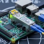
Before you touch ordering, confirm the exact transport layer in your design. Most Open RAN deployments map radio transport to Ethernet links, typically 10G, 25G, or 100G per interface, with strict reach requirements and defined optical budgets. You also need the transceiver cages and optics type supported by your switch, O-RU, O-DU, and aggregation gear. Vendors often ship different firmware behaviors for DOM parsing, so gather model numbers early.
Collect these items and stage them in a single worksheet:
- Link type and rate: 10GBASE-SR, 25GBASE-SR, 100GBASE-SR4, or 100GBASE-LR4 (IEEE 802.3).
- Fiber plant: OM3 vs OM4 vs OS2, expected link length, patch panel losses, and number of mated connectors.
- Switch and baseband interfaces: exact models and transceiver part numbers currently validated.
- DOM requirements: whether your management stack reads temperature, bias, and receive power thresholds.
- Environmental range: cabinet ambient temperature and airflow assumptions.
For authority on optical Ethernet standards, use [Source: IEEE 802.3]. For connector and cabling loss assumptions, align with [Source: ANSI/TIA-568] and vendor cabling guidance. For optics module electrical behavior and DOM interfaces, consult each vendor’s datasheet and your switch vendor’s compatibility matrix.

Step-by-step implementation: selecting optics that match Open RAN links
Follow these numbered steps during procurement and staging. Each step ends with an expected outcome you can verify before committing modules to the network.
Lock the Ethernet rate and optical standard
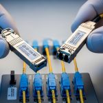
Choose the optics family that matches the interface speed and lane structure. For example, 10GBASE-SR uses single-lane optics in SFP+; 25GBASE-SR uses SFP28/25G; 100GBASE-SR4 uses four-lane optics in QSFP28. Confirm the interface type on the O-DU switch fabric and any inline media converters.
Expected outcome: a single standard per link (e.g., 25GBASE-SR on OM4) with no ambiguity between vendor-specific “25G” optics listings.
Compute reach using optical budget, not just “rated distance”
Take the rated reach from IEEE and vendor datasheets, then subtract real losses. Typical contributors: fiber attenuation (dB/km), splice loss, patch panel insertion loss, and connector mated loss. If your plant has many jumpers, the link can fail even when the raw length is under the module’s marketing distance.
Expected outcome: an optical budget margin of at least 3 dB for aging and cleaning variance, unless your vendor explicitly supports less.
Match fiber type and wavelength to the module
Open RAN sites frequently standardize on OM3 or OM4 for cost and availability. For multimode short reach, SR modules use 850 nm over OM3/OM4; for long reach, LR uses 1310 nm over OS2 single-mode. Do not substitute OS2-rated optics into an MMF plant; it will often fail link bring-up.
Expected outcome: correct fiber plant mapping: OM3/OM4 with SR at 850 nm, OS2 with LR at 1310 nm, and SR4 or LR4 matching the lane count.
Verify DOM behavior and thresholds against your control plane
Many Open RAN monitoring stacks rely on DOM to alert on rising receive power, temperature excursions, or optical output drift. Confirm your switch firmware reads the DOM and whether it enforces “known-good” transceiver vendor IDs. Some platforms block unsupported optics, even if they electrically link.
Expected outcome: validated DOM readout (temperature, bias current, TX power, RX power) in a lab port before field installation.
Confirm connector and polarity handling in the fiber plant
Multimode SR optics are sensitive to polarity and connector cleanliness. Ensure your transceiver type aligns with the cabling method (for MPO, confirm polarity and lane mapping). In live racks, mis-terminated polarity can present as intermittent CRC errors or link flaps.
Expected outcome: a documented patching diagram: which jumper goes from switch to patch panel and which polarity method is used.
Stage, label, and pre-test with deterministic traffic
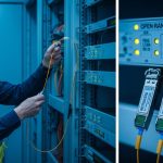
Before deployment, insert modules into a test switch or line card and run a traffic profile that exposes optical margin issues. Use continuous Layer 2 traffic (or vendor equivalent) while monitoring interface counters for CRC, symbol errors, and link retrains. Record baseline DOM values and compare after 24 hours.
Expected outcome: stable link for at least 24 hours, with no CRC/symbol error growth trend and DOM values inside vendor-recommended ranges.

Optical transceiver specs that matter for telecom selection
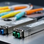
Use the table below to compare the most common short-reach choices for Open RAN fronthaul and midhaul. Treat “reach” as a ceiling under ideal conditions; your real constraint is the optical budget and polarity correctness.
| Module form factor | Standard | Wavelength | Typical reach (MMF) | Connector | Data rate | Operating temp | Notes for Open RAN |
|---|---|---|---|---|---|---|---|
| SFP+ | 10GBASE-SR | 850 nm | Up to 300 m (OM3) | LC | 10.3125 Gb/s | 0 to 70 C (typ.) | Good for shorter ToR-to-aggregation spans |
| SFP28 | 25GBASE-SR | 850 nm | Up to 100 m (OM3) / 150 m (OM4) | LC | 25.78125 Gb/s | -10 to 70 C (typ.) | Common midhaul and high-density links |
| QSFP28 | 100GBASE-SR4 | 850 nm | Up to 100 m (OM3) / 150 m (OM4) | MPO-12 | 103.125 Gb/s | 0 to 70 C (typ.) | Four-lane optics; polarity and MPO handling critical |
| QSFP28 | 100GBASE-LR4 | 1310 nm | Up to 10 km (OS2) | LC | 103.125 Gb/s | -5 to 70 C (typ.) | Use when spans exceed MMF budget |
Real-world module examples engineers often encounter include Cisco SFP-10G-SR, Finisar FTLX8571D3BCL, and FS.com SFP-10GSR-85. Always cross-check your switch’s transceiver compatibility list and the module’s DOM behavior in your firmware environment. For standard reach definitions and link characteristics, consult [Source: IEEE 802.3].
Pro Tip: In Open RAN cabinets, the most common “mystery” instability is not the transceiver optics itself but MPO polarity or dirty endfaces. A link can pass for hours, then start throwing CRC errors as temperature and connector micro-movements change alignment. Cleaning and repatching often fixes what looks like a marginal optical budget.
Decision checklist for telecom selection in Open RAN
Use this ordered list when choosing between OEM optics and third-party modules. Your goal is to minimize risk while meeting reach and operational constraints.
- Distance and optical budget: compute margin with measured patch cord and panel loss, not only datasheet reach.
- Switch and interface compatibility: match form factor (SFP+, SFP28, QSFP28), lane count, and switch vendor requirements.
- Fiber type alignment: OM3/OM4 for 850 nm SR; OS2 for 1310 nm or 1550 nm LR/ER.
- DOM support: confirm DOM readout works and alarms propagate in your telemetry stack.
- Operating temperature: verify module spec covers cabinet ambient plus airflow profile.
- Vendor lock-in risk: check whether your platform enforces vendor IDs or “known-good” optics lists.
- Interoperability testing effort: plan at least one lab port validation per optics family.
Common mistakes and troubleshooting for Open RAN optics
When optics fail, the symptoms are usually visible at the Ethernet layer. Here are the top field failure points, with root causes and exact fixes.
Failure point 1: Link does not come up after insertion
Root cause: wrong standard or wavelength/fiber mismatch (e.g., SR module in OS2 plant expectation, or LR module in MMF). Also common: unsupported optic on a switch that enforces transceiver ID checks.
Solution: confirm the transceiver standard (10GBASE-SR, 25GBASE-SR, 100GBASE-SR4, 100GBASE-LR4) and verify the switch compatibility matrix. In lab, try the module in a known-compatible port. If DOM is blocked, update switch firmware or use validated OEM/approved optics.
Failure point 2: CRC errors and intermittent link flaps
Root cause: dirty connectors, improper MPO polarity, or a connector/patching loss budget exceeded. Temperature changes amplify marginal alignment issues.
Solution: clean LC/MPO endfaces with proper fiber cleaning tools, then inspect with an endface scope. If MPO, verify polarity method and repatch using the correct lane mapping. Recompute optical budget using measured insertion loss from the patch panels.
Failure point 3: DOM alarms indicate low RX power or rising temperature
Root cause: aging optics, excessive bend radius in fiber management, or environmental overheating in a poorly ventilated rack. Another cause is inaccurate DOM interpretation in your monitoring scripts.
Solution: check DOM logs for trends, not only absolute thresholds. Verify fiber routing bend radius per manufacturer guidance and improve airflow. Calibrate your monitoring thresholds to match vendor datasheet recommended ranges.
Cost and ROI note for telecom selection
OEM optics typically cost more upfront but reduce compatibility risk. Third-party modules can be cheaper, yet your TCO may rise if you spend more labor on troubleshooting, RMA cycles, or firmware exceptions. In practice, many teams target a unit price delta while maintaining strict validation: buy a small batch, run 24-hour traffic plus DOM monitoring, then expand.
As a rough planning range, short-reach optics often fall into the low-to-mid hundreds of dollars per module for OEM, while third-party may be meaningfully lower but varies by rate and temperature grade. ROI improves when you prevent downtime and reduce truck rolls; if a rollout needs strict uptime, spending extra on validated optics and proper cleaning tooling usually beats “cheaper optics with higher failure investigation time.”

FAQ
Q: What should I verify first in telecom selection for Open RAN?
Start with the exact interface speed and standard on each port, then map it to the fiber type and wavelength. After that, confirm DOM support and switch compatibility in the vendor documentation. This order avoids wasted optics swaps during field staging.
Q: Are OM4 850 nm SR modules always safe for Open RAN fronthaul?
They are often appropriate for short reaches, but only if your optical budget has margin after patch panels, splices, and connector losses. If your plant is connector-dense or has long jumper runs, you can still fail even on OM4.
Q: How do I choose between OEM and third-party optics?
Use your switch vendor’s compatibility list as the primary rule. If third-party optics are allowed, enforce a lab validation step with deterministic traffic and DOM trend capture before scaling. The ROI depends on how quickly you can validate and how strict your uptime requirements are.
Q: What are the fastest troubleshooting checks for CRC errors?
Clean and inspect connectors, then verify MPO polarity if using MPO-12. Next, check DOM RX power trends for a gradual degradation pattern. Finally, recompute the optical budget using measured insertion losses.
Q: Do I need to worry about operating temperature for telecom selection?
Yes. Cabinet ambient plus airflow can exceed typical “room temperature” assumptions, especially near power shelves. Choose modules with an operating temperature range that covers worst-case conditions and monitor temperature via DOM.
Q: Where can I confirm standards and reach behavior?
Use IEEE 802.3 for Ethernet optical link characteristics, and cross-check each module vendor datasheet for DOM and optical power ranges. For cabling loss and connector practices, align with ANSI/TIA-568 and the cabling vendor’s guidelines.
Next step: build a