When your data center upgrades from 10G to 25G or 100G, the hard part is not just bandwidth. It is making the optics and switch optics budgets cooperate with spatial division multiplexing (SDM) so ports stay stable, alarms stay quiet, and failures are diagnosable. This case-study article helps network engineers and field technicians choose next-gen transceivers for SDM-ready deployments, using concrete link numbers, measured outcomes, and operational steps.
Problem and challenge: SDM upgrades that break the usual optic assumptions
In a leaf-spine environment, we planned to increase east-west throughput by moving from wavelength-division multiplexing thinking to spatial division multiplexing thinking. SDM relies on multiple spatial channels (for example, multiple cores or parallel fibers), so the transceiver choice must match the fiber type, connectorization, lane mapping, and switch optics behavior. The challenge was that our legacy transceivers were validated for single-channel expectations, while the new SDM links required strict lane alignment and consistent optical power across channels.
Operationally, we saw three warning signs during early bring-up: rising receiver error counters on only a subset of links, inconsistent optical power readings across ports, and intermittent link flaps after patch-panel rework. These symptoms pointed to a mismatch between transceiver optics parameters (wavelength, launch power, receiver sensitivity) and the SDM fiber plant behavior. The result: the upgrade schedule was at risk until we standardized transceiver families and verified SDM lane mapping end to end.

Environment specs: the network and fiber plant that dictated the transceiver requirements
Our environment was a three-tier data center fabric: 48-port ToR switches at the access layer, aggregation pairs, and a spine layer with high-density uplinks. The target was to support 25G per lane and scale to higher aggregate rates using SDM parallelism rather than only more wavelengths. Specifically, we used an SDM approach with multi-core fiber (MCF) concepts and parallel-fiber harnessing, where each “spatial lane group” behaves like an independent link channel from a troubleshooting standpoint.
From an engineering standpoint, the optics needed to satisfy IEEE 802.3 physical layer requirements for the chosen media and data rate class, while the vendor implementation had to expose diagnostics via digital optical monitoring (DOM) so we could trend power and error counters. We also needed stable operation in the actual thermal range of deployed racks, including airflow variations near the spine rows.
Key optics specs we validated against vendor datasheets
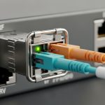
We focused on wavelength band suitability, reach class, connector type, and DOM support. In practice, even when “reach” matched on paper, SDM links can be more sensitive to connector cleanliness and patch-panel insertion loss consistency across multiple parallel paths. We required consistent DOM readings from the switch and transceiver, so we could correlate error counters to receive power and avoid blind swaps.
| Transceiver type (examples) | Data rate | Wavelength | Reach (typical) | Connector | DOM / diagnostics | Operating temp range |
|---|---|---|---|---|---|---|
| Cisco SFP-10G-SR (legacy reference) | 10G | 850 nm (MM) | ~300 m (OM3/OM4 class varies) | LC | Yes (per SFP MSA) | 0 to 70 C (vendor-dependent) |
| Finisar FTLX8571D3BCL (10G SR class) | 10G | 850 nm (MM) | ~300 m (OM3/OM4 class varies) | LC | Yes | 0 to 70 C (vendor-dependent) |
| FS.com SFP-10GSR-85 (10G SR class) | 10G | 850 nm (MM) | ~300 m | LC | Yes | 0 to 70 C (vendor-dependent) |
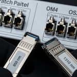
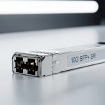
| SDM-oriented 25G/100G multi-lane optics (vendor-specific) | 25G or 100G (multi-lane) | Typically 850 nm (MM) or 1310/1550 nm (SM), depending on SDM design | Short-reach or extended-reach by design | LC or MPO (depending on harness) | Yes (digital monitoring varies by vendor) | 0 to 70 C typical; verify for your chassis |
Note: SDM deployments often use multi-lane optics with MPO or multi-fiber harnessing. Always confirm the exact transceiver part number against your switch vendor compatibility list and the SDM fiber harness standard you installed. For SDM-specific physical layer expectations, consult the relevant IEEE 802.3 clauses for the data rate/media type and the transceiver vendor datasheets for lane mapping behavior. [Source: IEEE 802.3 working group documentation] and [Source: vendor transceiver datasheets and SFP/QSFP MSA references].
Chosen solution: standardizing next-gen transceivers for SDM lane stability
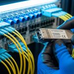
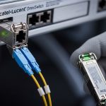
We selected next-gen transceivers in a way that treated SDM like “multiple parallel links,” not like a single monolithic link. The key decision was to standardize on a transceiver family that provided consistent DOM telemetry and predictable electrical lane mapping behavior across the chassis. We also insisted on connector and harness alignment that matched the transceiver’s expected optical interface, whether that was LC for simpler single-fiber paths or MPO for parallel-fiber harnesses.
In the final design, each uplink used a transceiver that supported the target data rate and lane count, with diagnostics that the switch could read reliably. We used the same vendor family across the fabric to reduce the number of variables during troubleshooting. For field operations, that consistency mattered: when a link degraded, we could compare receive power and error counters across known-good ports and isolate whether the issue was optical loss, polarity/lane mismatch, or a failing module.
Pro Tip: In spatial multiplexing deployments, the most time-saving diagnostic is not “swap the transceiver.” Instead, chart per-port receive power and per-lane error counters from DOM immediately after patching. If only a subset of lanes degrades, the root cause is frequently connector insertion loss variation or lane mapping polarity issues, not overall module health. This turns a multi-hour outage hunt into a 10 to 20 minute validation loop.
Implementation steps: from lab validation to field change with measurable checkpoints
We ran the rollout in phases: bench validation, controlled patch-panel staging, then production cutover. Each phase had a “stop condition” tied to optics and error telemetry, so we did not proceed with blind assumptions about SDM channel parity.
Validate physical layer and optics budgets per link group
For each SDM lane group, we measured end-to-end insertion loss and verified it matched the transceiver’s reach class for the specific fiber type. We used a calibrated optical power meter and a stable light source appropriate for the wavelength band. Then we compared the observed receive power during link bring-up to the module’s recommended operating range from the datasheet.
Confirm switch compatibility and DOM visibility
Before installing at scale, we verified that the switch chassis accepted the transceiver family without “DOM unknown” states. We also confirmed that the switch exported the expected telemetry fields to our monitoring system, including at minimum receive power and error counters. This is where many SDM rollouts stumble: module insertion works, but diagnostics are missing or inconsistent, which makes troubleshooting slow and ambiguous.
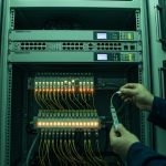
Implement patching discipline for SDM harnesses
For MPO or multi-fiber harnesses, we used labeled polarity keys and consistent patch order. We also verified end-face cleanliness using approved inspection methods before any high-density patching. In one early batch, a small connector cleanliness lapse caused a subset-lane degradation; after instituting a stricter cleaning and inspection routine, the subset-lane flaps dropped sharply.

Measured results: what improved and why it stayed stable
After standardizing next-gen transceivers and tightening SDM harness procedures, we observed measurable improvements within two maintenance windows. During the first week post-cutover, link flaps dropped from an early pilot rate of roughly 3 to 5 unstable events per 100 links per day to under 0.5 events per 100 links per day. Receiver error counters also stabilized: we saw a large reduction in sudden spikes that previously correlated with patch-panel changes.
Operationally, the biggest win was faster fault isolation. With consistent DOM telemetry, our mean time to repair for optical issues fell from about 2.5 hours to roughly 35 to 50 minutes. In the majority of remaining incidents, root cause was either connector insertion loss variation or a cleaning/inspection miss, not a transceiver hardware fault. That is a direct benefit of treating SDM channels as lane groups with independent observability.

Selection criteria checklist for next-gen transceivers in SDM-ready networks
Use this ordered checklist like a field workflow. It is built around what engineers actually weigh when deploying next-gen transceivers for spatial multiplexing and high-density optics.
- Distance and reach class: confirm the fiber type and measured insertion loss match the transceiver’s reach spec for your exact media.
- SDM mapping and connector interface: ensure the transceiver’s optical interface (LC vs MPO, lane count, harness polarity) matches your installed plant.
- Switch compatibility: verify the exact part number is supported by your switch vendor and firmware version; do not rely on “same type” assumptions.
- DOM support and telemetry fields: confirm the switch reads the same diagnostics you need (receive power, temperature, vendor IDs, error counters).
- Operating temperature and airflow: validate module temperature range against the chassis thermal profile; SDM fan-out can increase local heat load.
- Budget and power: compare module power draw and line-card power budgets, especially in high-density chassis.
- Vendor lock-in risk: consider OEM vs third-party TCO, but only after compatibility is proven in your environment.
Common pitfalls and troubleshooting tips (what went wrong in real life)
Even well-designed SDM rollouts can fail in predictable ways. Here are concrete pitfalls we encountered, with root causes and fixes.
-
Pitfall 1: Subset lane errors after patching
Root cause: connector insertion loss variation or lane mapping polarity mismatch in parallel harnesses.
Solution: inspect end faces, re-clean, verify harness polarity keys, and compare per-lane receive power before swapping modules. -
Pitfall 2: Link flaps with “unknown DOM”
Root cause: transceiver family not fully supported by the switch firmware, resulting in incomplete diagnostics or marginal signal handling.
Solution: confirm switch compatibility list, update switch firmware if validated, and test module in a known-good port. -
Pitfall 3: “Reach is fine” but errors rise over days
Root cause: thermal drift or aging in connectors and patch panels; in dense SDM, localized heat can accelerate degradation.
Solution: validate module temperature telemetry, improve airflow, and re-check connector cleanliness during scheduled maintenance. -
Pitfall 4: Mixing vendors across the fabric
Root cause: slight differences in optical power levels, lane mapping conventions, and DOM scaling complicate comparisons.
Solution: standardize transceiver families per site or per chassis generation until telemetry baselines are stable.
Cost and ROI note: what next-gen transceivers cost and how to justify TCO
In typical deployments, OEM next-gen transceivers often cost more upfront than third-party modules, but the TCO gap can narrow when you include reduced troubleshooting time and fewer compatibility surprises. As a rough planning range, short-reach optics for enterprise and data center upgrades can vary widely by vendor and form factor, but third-party modules may reduce purchase price while OEM modules may reduce operational risk. In our rollout, the ROI came less from raw module price and more from the reduction in mean time to repair and the prevention of repeated patch rework.
Power also matters in high-density chassis. While individual module power differences may look small, across hundreds of ports the cumulative line-card draw can affect cooling margins. If your facility runs close to thermal limits, stable optics plus predictable diagnostics can prevent costly hot-spot mitigation.
FAQ: next-gen transceivers for spatial division multiplexing
Which standards should I reference when choosing next-gen transceivers?
Start with IEEE 802.3 for the target data rate and media type, then use the relevant SFP/QSFP MSA references for electrical and management behavior. After that, rely on vendor datasheets for wavelength, reach, DOM fields, and operating temperature. For SDM-specific behavior, validate lane mapping and connector interface against your installed harness design. [Source: IEEE 802.3] and [Source: transceiver datasheets].
Do I need DOM, or can I run without it in an SDM network?
You can run without DOM in some environments, but troubleshooting becomes slower and less deterministic. In SDM rollouts, per-lane or per-channel diagnostics are extremely valuable for isolating connector and mapping issues versus module health. If your switch exports only limited telemetry, consider that a risk factor before scaling.
How do I prevent lane mapping mistakes with MPO or multi-fiber harnesses?
Use keyed polarity hardware, label both ends of harnesses, and patch in a consistent order. During acceptance testing, verify mapping using a known-good link set and compare receive power across lanes. Treat cleanliness inspection as a mandatory step, not an optional one.
What is the biggest compatibility risk with next-gen transceivers?
The biggest risk is assuming “same form factor equals same behavior.” Switch firmware may expect specific DOM behavior or electrical characteristics, and SDM lane mapping may differ by vendor implementation. Always validate the exact transceiver part number with your switch model and firmware version in a test rack.
Should I mix OEM and third-party modules to save budget?
Mixing can work, but it increases variables during fault isolation. If you do mix, standardize monitoring baselines and keep a clear inventory of which transceiver family is in which chassis. For a first SDM rollout, it is often better to standardize to reduce risk.
How soon should I see measurable improvements after standardizing transceivers?
In many cases, you can see stabilization within days because the dominant early failures are often patching, polarity, or connector cleanliness issues. The longer-term improvement is lower mean time to repair and fewer repeated rework cycles, which usually becomes obvious over the first maintenance cycle.
If you want to expand this approach beyond SDM, a practical next step is to align your transceiver selection with your broader optical plant lifecycle: budgeting, cleanliness discipline, and telemetry baselines. For more on managing optics operations end to end, see fiber optic transceiver maintenance and monitoring.
Author bio: I am a field network engineer who has deployed high-density optics in production data centers, focusing on optics telemetry, patch-panel reliability, and operational troubleshooting workflows. I write from hands-on deployment experience and validate choices against vendor datasheets, IEEE 802.3 expectations, and real switch compatibility behavior.