When your SONiC switch boots but links stay down, the culprit is often not routing or VLANs, but an incompatible SONiC SFP transceiver, missing DOM data, or optical/connector mismatch. This guide helps network engineers and operators validate SFP compatibility, read DOM telemetry reliably, and roll out optics safely in production. You will get a step-by-step implementation plan, a practical troubleshooting section, and an engineer-ready spec comparison table.
Prerequisites for SONiC SFP compatibility checks
Before touching optics, confirm your platform, image build, and management access so you can verify what SONiC expects from the transceiver. You will also need fiber test gear (at minimum, a visual fault locator for quick checks) and a known-good patching plan. Finally, plan for a maintenance window because transceiver swaps can flap links and impact spanning-tree and routing adjacencies.
What you should have on hand
- SONiC version matching your switch vendor support matrix (check release notes and platform docs).
- Console or SSH access with permissions to run operational commands and view logs.
- A list of intended optics part numbers (example: Cisco SFP-10G-SR or Finisar FTLX8571D3BCL or FS.com SFP-10GSR-85).
- Fiber polarity plan: LC connectors with correct transmit/receive mapping.
- DOM-capable modules and a plan to confirm DOM support (Digital Optical Monitoring over the SFP management interface).
Standards-wise, SONiC SFP compatibility typically hinges on how the switch driver interprets IEEE 802.3 optical reach/channel expectations and the transceiver’s management data. Most 1G/10G SR modules use 850 nm multimode signaling, commonly aligned with 802.3z/802.3ae behavior, while LR modules use 1310 nm single-mode optics. For the wiring and fiber plant side, ANSI/TIA cabling practices help you avoid avoidable link failures. See [Source: IEEE 802.3] and [Source: ANSI/TIA-568] for baseline reference.

Step-by-step: Validate and roll out SONiC SFP modules safely
Use this numbered implementation flow to minimize downtime. Each step includes the expected outcome so you can stop early if something is off. The goal is not just “link comes up,” but “SONiC sees correct DOM, matches expected optics characteristics, and behaves consistently across reboots.”
Confirm platform optics expectations and driver support
Start by identifying the exact switch model and SONiC build. SONiC images vary in how they load platform-specific drivers and whether DOM and threshold alerts are enabled by default. Check the vendor documentation for the supported transceiver families and any known quirks.
Expected outcome: You confirm the platform supports the intended SFP type (1G/10G/25G where applicable) and that the SONiC image includes the relevant driver and transceiver management support.
Pre-check optics part numbers against compatibility targets
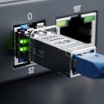
Before insertion, verify the exact SKU and wavelength class. In the field, I have seen “looks identical” optics fail because one module is a different speed grade or uses a different vendor calibration profile. For example, 10G SR modules should be 850 nm multimode with LC connectors, while LR modules are typically 1310 nm single-mode.
Expected outcome: Your optics list is consistent with the port speed configuration and fiber plant (MMF vs SMF, LC vs other connector types).
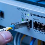
Insert optics and confirm link state transitions
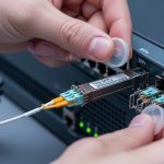
Power state matters. For many switches, inserting an SFP while the system is live is supported, but you should still plan for link renegotiation and possible interface flaps. After insertion, check interface operational status and counters.
Expected outcome: Interfaces transition to up/up (or expected admin/oper state) without persistent flapping.
Read DOM telemetry in SONiC and verify thresholds
DOM data tells you whether the transceiver is alive and whether optical power levels are in a healthy range. SONiC commonly exposes transceiver details through platform tooling; the exact command names can vary by SONiC release and vendor integration. On a working system, you should see values such as temperature, supply voltage, laser bias/current, and received optical power.
Expected outcome: DOM fields populate and remain stable after a few minutes. You do not see “DOM not present” or missing sensor readings.
Pro Tip: In production, don’t wait for user traffic to validate optics. I routinely check DOM right after link up and again after 5 to 10 minutes; marginal optics often show drifting received power or laser bias creep before they fully fail under sustained load.
Confirm VLAN and forwarding behavior after optics are stable
Once the physical layer is stable, verify the L2/L3 behavior you care about. If you are using VLANs on the interface, confirm trunk/access configuration and that tagged frames are forwarded correctly. In SONiC deployments, optics validation should precede VLAN troubleshooting, because a down/up mismatch can masquerade as a VLAN misconfiguration.
Expected outcome: VLAN membership is correct, and you see expected MAC learning and L2 forwarding behavior.
Lock in a safe rollback plan
Keep a known-good transceiver on hand for each wavelength class and speed grade. Before a wider rollout, test at least one “hot swap” event and confirm the interface returns to the correct state after reboot. Document the exact transceiver part numbers and port mapping so rollback is fast and deterministic.
Expected outcome: You can revert to a known-good optics set within minutes, with minimal configuration drift.

Which SONiC SFP types match your reach and fiber plant?
The right SONiC SFP choice depends on distance, fiber type, and budget. In practice, I pick optics based on the existing plant (MMF vs SMF), then verify SONiC driver compatibility and DOM behavior. When you mix optics types on similar ports, keep a strict naming and documentation system to avoid “wrong wavelength” incidents during maintenance.
Common optics profiles engineers deploy
- 10G SR (850 nm, MMF): common for top-of-rack to server connections in data centers.
- 10G LR (1310 nm, SMF): common for longer intra-facility runs and aggregation links.
- 10G ER (1550 nm, SMF): used when you must extend reach further, often with tighter power budgets.
Key specifications comparison table
Use this table to quickly compare typical SFP optics characteristics. Always confirm exact thresholds (Tx/Rx power, DOM support) in the vendor datasheet for the specific SKU you plan to deploy.
| Optics type | Wavelength | Typical connector | Typical reach | Data rate | DOM | Operating temperature | Examples (part numbers) |
|---|---|---|---|---|---|---|---|
| 10G SR | 850 nm | LC (MMF) | Up to ~300 m (MMF, depends on fiber grade) | 10G | Usually supported | Often 0 to 70 C (commercial) or -40 to 85 C (extended) | Cisco SFP-10G-SR; Finisar FTLX8571D3BCL; FS.com SFP-10GSR-85 |
| 10G LR | 1310 nm | LC (SMF) | Up to ~10 km (depends on optics and fiber) | 10G | Usually supported | Often 0 to 70 C or -40 to 85 C | Cisco SFP-10G-LR; Finisar FTLX1471D3BCL; FS.com SFP-10GLR-85 |
| 10G ER | 1550 nm | LC (SMF) | Up to ~40 km (depends on optics) | 10G | Usually supported | Often 0 to 70 C or -40 to 85 C | Vendor-specific ER SKUs (confirm datasheet) |
For optical reach and interface behavior, align with the applicable IEEE 802.3 PHY expectations and the transceiver datasheet. For cabling and polarity practices, align with ANSI/TIA-568. [Source: IEEE 802.3] [Source: ANSI/TIA-568]
IEEE 802.3 optical Ethernet references
Compatibility checklist engineers actually use for SONiC SFP
When I audit optics during a SONiC rollout, I treat transceivers like software dependencies: verify compatibility, validate telemetry, and reduce unknowns. The checklist below is ordered the way field teams should think—starting with physics (distance and fiber) and ending with operational safety (DOM and rollback).
- Distance and link budget: confirm MMF vs SMF and expected attenuation at the wavelength.
- Switch port speed and media type: ensure the port is configured for the correct speed (and that the optics matches it).
- Connector standard and polarity: LC connectors and correct Tx/Rx mapping are non-negotiable.
- DOM support and sensor mapping: verify SONiC can read temperature, bias, and received power.
- Operating temperature range: ensure the transceiver meets the ambient conditions in your rack.
- Vendor lock-in risk: decide whether you trust third-party modules and how you will validate them at scale.
- Power budget and optics class: check Tx power and receiver sensitivity in the datasheet, not just “reach.”
- Field failure history: track DOA rates and RMA turnaround for the module family you plan to buy.
Common SONiC SFP mistakes and troubleshooting tips
Most SONiC SFP failures are predictable. The trick is to isolate whether the problem is physical optics, transceiver management (DOM), or higher-layer configuration. Below are the top failure modes I see during deployments.
Troubleshooting failure point 1: Link down due to fiber polarity or wrong mapping
Root cause: Tx and Rx swapped, or patch panel remapped during maintenance. This is the most common “everything looks right” issue. DOM may still show values, but received power will be near unusable.
Solution: Verify polarity at both ends and re-terminate or re-patch to ensure Tx to Rx. Then re-check received optical power in DOM and confirm the interface becomes up/up.
Troubleshooting failure point 2: DOM not present or unstable sensor values
Root cause: A module that does not fully implement expected DOM behavior, or a SONiC driver/firmware integration mismatch. Some third-party optics are “DOM compatible” but not consistent in thresholds or sensor naming.
Solution: Swap the module with a known-good DOM-capable transceiver of the same type. If DOM still fails, confirm your SONiC release includes the relevant platform integration and check system logs for transceiver I2C/EEPROM read errors.
Troubleshooting failure point 3: Link flaps after traffic starts
Root cause: Marginal optical budget, dirty connectors, or overheating. In racks with poor airflow, temperature can drift quickly and push laser bias outside safe ranges.
Solution: Clean LC connectors using proper lint-free wipes and isopropyl alcohol approved for optics, then re-seat modules. Validate DOM stability after 5 to 10 minutes of idle and after a short traffic burst.

Cost, ROI, and transceiver sourcing strategy for SONiC
Optics costs swing based on OEM vs third-party and whether you require extended temperature parts. In typical enterprise and data center buys, OEM-branded 10G SR modules often cost more per unit, while compatible third-party optics can reduce upfront spend but increase validation time. For ROI, count not only purchase price but also the labor hours spent verifying DOM and diagnosing early failures.
Realistic price ranges: many 10G SR optics land roughly in the mid tens to low hundreds of USD per module depending on vendor and temperature grade; OEM can be higher. TCO improves when your validation pipeline is mature: you can test DOM and link behavior automatically during staging, then scale purchases with fewer “surprise” RMAs.
Operational note: if you plan large-scale SONiC deployments, standardize on 1 to 2 transceiver families per wavelength class and keep spares. This reduces troubleshooting variability and speeds up incident response.
FAQ
What exactly makes a SONiC SFP “compatible”?
Compatibility is usually a mix of physical layer support (correct wavelength, speed, connector type) and management layer behavior (DOM availability and correct EEPROM interpretation). Even if the link comes up, inconsistent DOM can break monitoring and alarms.
Can I use third-party SFPs with SONiC?
Yes, many operators do, but you must validate DOM readings, sensor thresholds, and stability under load. Treat optics as a tested dependency: stage-test one batch, then standardize part numbers.
Why does the interface show up but traffic fails?
Most often it is fiber polarity, VLAN/trunk configuration, or an optics budget mismatch that only appears under sustained traffic. Check DOM received power and confirm L2 forwarding for the VLAN before changing routing.
How do I confirm DOM is working on my SONiC switch?
Use the SONiC operational tools for transceiver diagnostics and verify that DOM sensors populate and remain stable. If DOM is missing, check logs for EEPROM/I2C read failures and try a known-good module.
What temperature range should I require for data center optics?
At minimum, match the transceiver’s rated operating range to your rack ambient and airflow assumptions. In hot aisle or constrained airflow designs, prefer extended temperature modules when available and confirm thermal stability with DOM.
What is the fastest way to isolate an optics incident?
Swap with a known-good module of the same type, then re-check DOM and link state. If the problem follows the module, it is optics-related; if it stays on the port, inspect the cage, cabling, and SONiC logs.
If you implement the validation flow above, you will catch most SONiC SFP issues before they become outages. Next, connect optics readiness to your forwarding design by reviewing VLAN trunk and interface validation.
Author bio: I have deployed SONiC-based leaf-spine and access networks using hands-on fiber bring-up, VLAN rollouts, and DOM-driven monitoring. I focus on practical compatibility testing, rapid rollback design, and measurable optical health verification in production.