Small to mid-sized businesses often discover their backup plan fails at the moment of need: mismatched optics, marginal fiber runs, or switch incompatibility. This quick reference focuses on SMB fiber solutions using fiber SFP options for resilient failover, so IT and field teams can select, validate, and deploy backup links with fewer surprises. You will get practical selection criteria, a specs comparison table, troubleshooting pitfalls, and a realistic cost and ROI view.
Why SFP-based fiber backups break in the real world

In backup topologies, the optics path is exercised less often than the primary link, so latent issues go unnoticed until an outage triggers failover. Common failure modes include wrong wavelength (e.g., 850 nm vs 1310 nm), incorrect fiber type (OM3 vs OS2), and transceiver settings that do not negotiate properly with the switch. IEEE 802.3-compliant optics can still behave differently across vendors due to implementation details, so compatibility testing matters as much as raw reach.
For SMB fiber solutions, the goal is to match data rate, optical wavelength, connector type, and DOM behavior to your exact switching platform. Many teams also underestimate environmental constraints: temperature extremes and dusty patch panels can push optical power into the margin where link stability degrades.
For authority on Ethernet physical layer behavior and link requirements, see IEEE 802.3. For operational transceiver guidance and compliance expectations, review vendor and module datasheets for your specific SFP models.
Fiber SFP options that fit SMB backup links
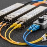
Most SMB backup designs use single-mode for longer runs and multi-mode for short, cost-sensitive intra-campus links. SFP transceivers are widely available at 1G and 10G speeds, which makes them a practical fit for many SMB switches that support SFP/SFP+ uplinks and stacking.
Typical backup link patterns
- Intra-site backup: 1G or 10G over OM3/OM4 within a building or campus, often under 300 m.
- Inter-building backup: 1G or 10G over OS2 single-mode fiber for 500 m to several kilometers.
- Router-to-switch failover: SFP on both ends, with routing convergence handled by the edge device.
Key optical choices (what you must match)
- Wavelength: 850 nm for multimode; 1310/1550 nm for single-mode.
- Reach: Confirm against fiber category (OM3/OM4/OS2) and measured link loss.
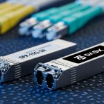
- Connector: LC is most common; confirm patch panel and bulkhead hardware.
- DOM support: Digital Optical Monitoring helps with proactive maintenance, but behavior varies by switch.
- Temperature range: Industrial (-40 to 85C) vs standard (0 to 70C) can matter outdoors.
Specs comparison table (common SFP backup optics)
Use this table to anchor your initial shortlist, then confirm exact part numbers against your switch vendor compatibility list and the SFP datasheet.
| Spec | 10G SFP+ SR (850 nm) | 10G SFP+ LR (1310 nm) | 1G SFP SX (850 nm) | 1G SFP LX (1310 nm) |
|---|---|---|---|---|
| Data rate | 10.3125 Gbps | 10.3125 Gbps | 1.25 Gbps | 1.25 Gbps |
| Typical reach | Up to 300 m on OM3 (varies by vendor) | Up to 10 km on OS2 (varies by vendor) | Up to 550 m on OM2 / 300 m on OM3 (varies) | Up to 10 km on OS2 (varies) |
| Fiber type | Multimode (OM3/OM4) | Single-mode (OS2) | Multimode (OM2/OM3) | Single-mode (OS2) |
| Connector | LC | LC | LC | LC |
| DOM | Often supported; verify switch compatibility | Often supported; verify switch compatibility | Often supported; verify switch compatibility | Often supported; verify switch compatibility |
| Operating temperature | Commonly 0 to 70C (some -40 to 85C exist) | Commonly 0 to 70C (some -40 to 85C exist) | Commonly 0 to 70C | Commonly 0 to 70C |
| Representative part numbers | Cisco SFP-10G-SR, Finisar FTLX8571D3BCL, FS.com SFP-10GSR-85 | Cisco SFP-10G-LR, FS.com SFP-10GLR, Finisar FTLX1311D3BCL | Common 1G SX SFP modules (vendor-specific) | Common 1G LX SFP modules (vendor-specific) |
Deployment scenario: failover uplink in a 48-port SMB core
In a typical SMB environment, a 48-port ToR or access switch provides uplinks to a core router and a separate backup path. Example: a 10G-based leaf uplink from a 48-port switch to a router, with the backup using a second 10G SFP+ link over OS2 fiber across two buildings. The primary uses 10G LR (1310 nm) for reliability over roughly 2.5 km, while the backup also uses 10G LR but on a physically separate fiber route to reduce single-cable risk.
Field implementation details that matter: confirm LC polarity end-to-end, label patch cords, and verify optical budget using measured link loss. In one deployment, engineers targeted at least 3 dB of optical margin after accounting for connectors, splices, and patch panels; when margin dropped below that threshold, link flaps appeared after temperature swings in the IDF room.
Operationally, configure link monitoring so that failover triggers on interface down events, not just higher-layer keepalives. Then test failover twice: once during normal temperature and again after the facility HVAC cycles to mimic worst-case optical conditions.
Selection criteria checklist for SMB fiber solutions
Use this ordered checklist to reduce compatibility and margin failures. For SMB fiber solutions, the cheapest optic is rarely the cheapest outcome once you include truck rolls and downtime.
- Distance and fiber type: Measure actual run length and confirm OM3/OM4/OS2. Do not rely on “estimated” fiber labels.
- Data rate and link mode: Match SFP vs SFP+ (10G requires SFP+ in most platforms). Verify the switch supports that speed on the target port.
- Wavelength and reach class: Ensure 850 nm modules go to multimode fiber and 1310/1550 nm modules go to single-mode fiber.
- Connector and polarity: Confirm LC connector type and polarity configuration (especially with fiber patch panels).
- DOM and monitoring: Check whether your switch reads DOM thresholds correctly. Some third-party modules can be detected but not fully monitored.
- Operating temperature: If optics sit in unconditioned cabinets, prefer -40 to 85C rated modules.
- Switch compatibility and lock-in risk: Cross-check vendor compatibility lists and consider whether you want to standardize on one OEM ecosystem.
- Optical budget margin: Use measured attenuation (including connectors/splices) and keep a margin target (commonly 3 dB or more for stability).
- Warranty and RMA turnaround: For backup links, prioritize fast replacement logistics over marginal unit cost.
Pro Tip: Many “it should work” failures come from polarity and patch panel wiring, not from the transceiver itself. Before blaming optics, verify Tx-to-Rx mapping with a continuity test or a known-good test cord, then re-check link stability after reseating connectors.
Common mistakes and troubleshooting for SFP backup failures
Below are concrete failure modes you can recognize quickly in the field. Each includes root cause and an action plan.
Wrong wavelength for the installed fiber
Symptoms: Link never comes up, or it comes up intermittently during reseating.
Root cause: 850 nm (SR/SX) optics installed on OS2 single-mode, or 1310 nm (LR/LX) optics installed on OM multimode.
Solution: Confirm fiber type at the patch panel and compare to optic wavelength labeling. Replace with the correct class (e.g., 10G SR only on OM3/OM4).
Insufficient optical margin due to hidden loss
Symptoms: Link is up initially, then flaps after temperature changes or after cable movement.
Root cause: Measured attenuation exceeded the practical optical budget due to additional connectors, dirty bulkheads, or unplanned splices.
Solution: Re-measure using an optical power meter and light source at the correct wavelength, clean connectors, and verify budget with a margin target (often > 3 dB).
DOM or vendor compatibility quirks
Symptoms: Link works but monitoring shows “DOM threshold exceeded,” “unknown transceiver,” or syslog alarms.
Root cause: The switch’s DOM interpretation differs across platforms; some third-party SFPs report values that trigger warnings.
Solution: Validate with your switch model and firmware. If alarms create operational noise, confirm whether alarms are cosmetic or correlate with real power levels; in some cases, standardize on a vendor-approved module.
Fiber polarity reversal after patch cord changes
Symptoms: Link down after maintenance, sometimes restored by swapping patch cords.
Root cause: Tx/Rx reversed on one end due to patch panel reconfiguration.
Solution: Verify polarity end-to-end. Re-seat and, if needed, swap A/B on the LC duplex connectors.
Cost and ROI note for SMB fiber solutions
For SMB fiber solutions, typical street pricing varies by speed and brand, but realistic ranges are useful for planning. OEM 10G SR and LR SFP+ modules often cost more per unit than third-party, but they may reduce downtime risk and improve monitoring consistency; third-party SFPs can be a cost win if compatibility is verified.
- 10G SFP+ SR (850 nm): commonly budget for roughly $50 to $250 per module depending on brand and warranty.
- 10G SFP+ LR (1310 nm): commonly roughly $80 to $350 per module.
- 1G SFP: often $20 to $120 per module.
TCO should include: spares inventory (at least one spare per critical link), labor/truck rolls for troubleshooting, and downtime cost. A conservative ROI model assumes one avoidable incident can offset the price premium of a compatible OEM module within a single year, especially for backup paths that must succeed during outages.
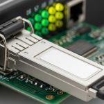
Visual reference: what to inspect before you trust the link
Use these inspection cues during deployment and maintenance. They are not a replacement for power measurements, but they catch frequent physical issues.
FAQ for SMB fiber solutions using SFP backups
What is the fastest way to confirm an SFP will work on my switch?
Check the switch vendor’s optics compatibility list for your exact model and firmware version, then validate with a short test loop in the same port. If you cannot find a list, test in a controlled window and verify link stability and DOM readings under temperature change.
Should SMB fiber solutions use multimode or single-mode for backup?
Use single-mode (OS2) when the run crosses buildings, has uncertain future length, or must tolerate higher loss and longer distances. Use multimode (OM3/OM4) for short intra-site runs where cost matters and the fiber plant is known-good.
Do I need DOM support for a backup link?
DOM is not strictly required for basic link operation, but it is valuable for proactive maintenance and early fault detection. Some switches read DOM differently, so verify that DOM alarms do not become noise during normal operation.
How much optical margin should I target for failover stability?
A common field target is at least 3 dB margin after accounting for connectors, splices, and patch cords. If your environment has temperature swings or frequent cable handling, aim higher and prioritize clean connectors.
Can I mix OEM and third-party SFP modules on the same switch?
Often yes, but monitoring behavior and compatibility can vary by platform. To minimize operational risk, standardize module types across redundant links, and verify that both ends of the backup path behave consistently.
What should I log during a failover test?
Capture interface up/down events, link error counters, and any DOM threshold warnings. Also record time-to-converge at the routing layer so you can confirm that optics recovery aligns with your business continuity objectives.
If you want to reduce failures further, pair this SFP selection workflow with a repeatable fiber validation and labeling process; start with fiber-optic-failover-checklist for a deployment-ready checklist.
Author bio: I have deployed fiber Ethernet failover for SMB and mid-market networks, including SFP/SFP+ optics validation, optical budget measurement, and field troubleshooting under tight maintenance windows. I write from hands-on experience with power meters, DOM monitoring, and switch compatibility testing practices grounded in vendor datasheets and IEEE Ethernet requirements.