In a campus network, the moment a fiber link misbehaves, every dependent service feels it: routing flaps, voice quality drops, and backups crawl. This article helps network engineers and data center technicians choose a single-mode transceiver campus solution that matches distance, switch requirements, and real operating conditions. You will get practical selection criteria, a specs comparison table, and troubleshooting patterns pulled from field deployments.
Why single-mode optics decide campus reliability
Single-mode fiber and optics are designed for long-reach links by launching light into the fundamental mode with tight spectral control. In IEEE 802.3, the physical layer definitions for Ethernet over fiber specify reach targets, link budgets, and optical parameters that transceivers must meet for interoperability. In practice, campus links fail less often when the selected module aligns with the switch vendor’s supported optics list and the fiber plant’s real attenuation and connector losses. For a single-mode transceiver campus build, the goal is predictable optics behavior across temperature swings, not just meeting nominal distance.
What engineers actually measure before buying
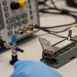
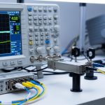
Before you select a module, measure or request: end-to-end fiber attenuation at the relevant wavelength band, connector and splice loss, and polarity correctness. A field engineer will typically verify with an OTDR trace and confirm the link budget fits the planned optics reach with headroom for aging. Many campus outages trace back to marginal patch panel workmanship or a swapped polarity jumper rather than the transceiver itself. Treat the fiber plant as part of the optics system, not a background detail.
Pro Tip: If you inherit a campus fiber plant with unknown history, validate with OTDR and then pick transceivers with strong DOM telemetry support; you can catch degrading receive power early instead of waiting for intermittent packet loss.
Key specifications that must match your campus link
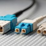
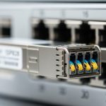
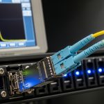
Single-mode transceivers come in multiple data rates and wavelength families, most commonly 1310 nm and 1550 nm. The wavelength determines dispersion behavior and typical reach for a given optical power class, while the connector type (LC is most common) must match the patch panels. Temperature range matters too: modules rated for extended commercial or industrial conditions will be more stable in thermally stressed wiring closets. Always align module optics parameters with the switch’s supported transceiver criteria and the network’s expected link budget.
Single-mode transceiver specs comparison (typical campus choices)
| Parameter | 10G SM SR (1310 nm, example) | 10G SM LR (1310 nm, example) | 25G/40G/100G SM (1550 nm family) |
|---|---|---|---|
| Typical wavelength | 1310 nm | 1310 nm | 1550 nm (varies by standard) |
| Typical reach class | Up to ~10 km | Up to ~40 km | Up to ~80 km (or more, depending on rate) |
| Connector | LC duplex | LC duplex | LC duplex (common) |
| DOM support | Often present (info varies) | Often present | Common; check vendor support |
| Power consumption | ~1–3 W typical | ~1.5–4 W typical | ~3–8 W typical (rate dependent) |
| Operating temperature | Commercial or extended options | Commercial or extended options | Check datasheet explicitly |
| Standards alignment | IEEE 802.3 fiber PMD | IEEE 802.3 fiber PMD | IEEE 802.3 relevant PMD |
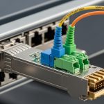
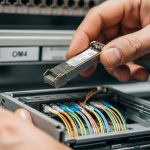
When you compare models, include at least: wavelength, reach, power class, DOM capability, and the exact connector and transceiver form factor (SFP+, SFP28, QSFP+, QSFP28, QSFP56). For concrete examples, engineers often evaluate vendor optics such as Cisco SFP-10G-SR, Finisar FTLX8571D3BCL, or FS.com SFP-10GSR-85 for cost and availability, but the campus decision still hinges on the correct single-mode wavelength and reach class. For standards grounding, reference IEEE 802.3 for the specific PMD targets and [Source: IEEE 802.3].

Selection criteria checklist for a single-mode transceiver campus build
Buying optics is not a one-dimensional “reach” problem; it is a compatibility and operational risk problem. Use this ordered checklist in procurement and lab validation, and you will avoid most real-world failures.
- Distance vs. link budget: Confirm planned fiber length plus margin, connector losses, and splice count at the target wavelength. Aim for headroom beyond the rated reach.
- Data rate and lane mapping: Match the transceiver to the switch port speed and any breakout mode (for example, 40G to 4x10G behavior depends on platform).
- Switch compatibility: Verify the switch vendor’s optics compatibility list and test in a maintenance window if you use third-party modules.
- DOM support and monitoring: Confirm the module supports digital optical monitoring (DOM) and that the switch reads key thresholds like receive power. Some platforms show DOM but do not alert reliably.
- Operating temperature and airflow: Check the module’s rated temperature range and compare with the closet environment. A module rated for extended temperature is often worth it in hot aisles.
- Connector standard and polarity: Ensure LC duplex type matches, and validate TX/RX polarity using a consistent labeling scheme at patch panels.
- Vendor lock-in risk: Balance OEM assurance against third-party availability. Maintain spares that are interchangeable only when the switch confirms compatibility.
Deployment scenario: leaf-spine campus with long links
Consider a campus with a leaf-spine topology where 48-port ToR switches connect to two spine switches using 10G uplinks. Each leaf has two uplinks, and the farthest building has a measured fiber length of 6.5 km with approximately 1.2 dB total connector loss and several splices adding 0.3 dB extra attenuation at 1310 nm. Engineers choose an appropriate single-mode module class that comfortably exceeds the planned reach, and they require DOM so the operations team can watch receive power trends during peak summer heat. In this environment, a module like a 1310 nm single-mode long-reach SFP+ class is often selected, then validated with loopback fiber tests and port-level counters before cutover.

Common mistakes and troubleshooting patterns
Even when procurement is correct, field issues can appear. Here are frequent failure modes with root cause and practical solution steps.
Link comes up intermittently, then drops during temperature swings
Root cause: The module is operating near or beyond its effective thermal envelope, or airflow is blocked in the wiring closet. Solution: Confirm module temperature rating and improve airflow; re-seat the module and check for dust on connectors. Use DOM telemetry to track receive power and bias drift over time.
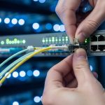
No link light after installation, but fibers look “connected”
Root cause: TX/RX polarity is reversed or a patch cord was swapped during labeling. Solution: Validate polarity at both ends: confirm the transceiver TX mates to the far-end RX. Follow a consistent polarity method (often “A-to-B” with labeled jumpers) and document it for future maintenance.
Port flaps with CRC errors after a “successful” optical bring-up
Root cause: Fiber attenuation is higher than expected due to damaged connectors, excessive bend radius, or an unaccounted splice. Solution: Run an OTDR trace and re-clean connectors with proper lint-free procedures; replace suspect patch cords. Compare DOM receive power against recommended thresholds and confirm the link budget includes margin.
Switch rejects third-party optics or shows “unsupported transceiver”
Root cause: The module’s EEPROM identification or timing does not align with platform expectations. Solution: Use the vendor compatibility list, update switch firmware when allowed, and test a spare module in a controlled port before scaling.

Cost and ROI: what you should budget for total ownership
OEM optics often cost more per module, but they reduce procurement friction and compatibility risk. Typical street pricing varies widely by rate and reach; as a rough expectation, 10G single-mode optics frequently land in the range of tens of dollars to low hundreds per module depending on reach class and brand, while higher-rate coherent or long-reach options can be several hundred to over a thousand per unit. For ROI, include power draw (fanout and switch power budgeting), failure rates, and labor hours for troubleshooting. In many campuses, the biggest cost driver is not the optics price; it is downtime during maintenance windows, so DOM visibility and predictable compatibility can pay back quickly.
If you want a related angle on how to plan fiber runs and patching discipline, see fiber cabling polarity best practices.
FAQ
What wavelength should I pick for a single-mode transceiver campus link?
Most campus Ethernet optics use 1310 nm for common single-mode SFP/SFP+ long-reach classes, while 1550 nm is common for longer-reach families at higher rates. Your choice should be based on the module’s reach rating for the exact standard and the measured fiber attenuation at that wavelength. Always verify the switch port supports that wavelength family.
Do I need DOM for campus operations?
DOM is strongly recommended because it provides receive power and temperature trends that help detect degradation before outages. Some switches expose DOM data but do not generate actionable alerts, so confirm your monitoring workflow. In practice, field teams use DOM graphs during seasonal transitions and during major maintenance windows.
Can I mix OEM and third-party single-mode transceivers on the same switch?
Sometimes yes, but it depends on the switch model, firmware, and the optics compatibility list. Mixing brands without validation can cause “unsupported transceiver” states or subtle performance issues. The safe approach is to test each brand in a maintenance window and standardize what is deployed per platform.
What is the most common reason for “no link” on fiber campus ports?
The most common cause is polarity reversal (TX/RX swapped) or a mislabeled patch cord. The second most common cause is dirty connectors or damaged fiber ends. Use a consistent labeling method and confirm polarity at both ends before blaming the module.
How much margin should I keep versus the transceiver reach rating?
Keep practical headroom for connector loss, splices, aging, and measurement uncertainty. A common engineering mindset is to treat rated reach as a ceiling and design for a buffer so the link remains stable under worst-case conditions. Use OTDR or attenuation measurements to quantify that buffer.
Where can I verify the Ethernet fiber PMD requirements?
IEEE defines the physical layer targets for Ethernet over fiber in its Ethernet standards, which are the baseline for reach and optical behavior. For platform-specific behavior, rely on the switch vendor datasheets and optics compatibility documentation. Consult [Source: IEEE 802.3] for the standard and the transceiver datasheet for DOM and temperature limits.
Choosing the right single-mode transceiver campus optics is less about chasing maximum reach and more about matching standards, compatibility, and fiber reality. Next, use fiber cabling polarity best practices to lock in patching discipline before you scale across buildings.
Author bio: I design