When telecom teams modernize access and aggregation sites, they often hit a painful bottleneck: transceiver choice becomes a reliability and upgrade-speed problem, not just a bill-of-materials decision. This article focuses on SFP use cases in real telecom-style networks, showing how an engineering team selected, deployed, and troubleshot SFP optics to keep traffic moving during a capacity refresh. You will get implementation steps, measured results, and a practical checklist you can apply to your own switch and fiber plant.

Problem and challenge: keeping traffic stable during a telecom capacity refresh
In a multi-tenant telecom environment, a regional operator planned a leaf-spine style upgrade across four aggregation sites. The challenge was that legacy uplinks were already running at 10G with mixed vendor optics, while new transport demanded predictable link behavior during cutovers. The operations team needed a transceiver strategy that would reduce “mystery link flaps” and shorten maintenance windows, especially when technicians were replacing modules under time pressure.
The key constraint was compatibility with switch optical diagnostics and DOM telemetry, because the sites used centralized monitoring that flagged abnormal laser bias and optical power drift. In practice, that meant choosing SFP optics that supported Digital Optical Monitoring and matched the expected fiber type and wavelength plan. The team also had to consider power and thermal behavior inside 1U and 2U chassis with constrained airflow, where a marginal module can increase fan duty cycle and raise the probability of intermittent faults.
Environment specs: fiber plant, switching targets, and optical requirements
Before selecting any optics, the team documented the physical plant and switch capabilities. The aggregation switches supported 10G SFP+ uplinks with standard LR/SR wavelength profiles, and the monitoring system queried DOM values for threshold alarms. Fiber runs varied by site: intra-building links were short and used OM3 or OM4 multimode patching, while some cross-floor and cross-cabinet runs were longer and required careful budgeting.
Reference optical targets used in the project
They standardized on two optics families: 10GBASE-SR for multimode and 10GBASE-LR for longer reach. For the migration windows, they prioritized modules that had consistent DOM ranges across vendors to avoid alert noise. Where QSFP was used for higher-speed spines, the team kept the SFP scope limited to access and aggregation edges to control variables.
| Parameter | 10GBASE-SR (SFP+) | 10GBASE-LR (SFP+) | 10GBASE-SR (QSFP+) |
|---|---|---|---|
| Data rate | 10.3125 Gb/s | 10.3125 Gb/s | 10.3125 Gb/s |
| Nominal wavelength | 850 nm | 1310 nm | 850 nm |
| Typical reach | Up to 300 m on OM3, up to 400 m on OM4 (spec dependent) | Up to 10 km on single-mode (spec dependent) | Up to 300 m on OM3, up to 400 m on OM4 (spec dependent) |
| Connector | LC duplex | LC duplex | LC duplex (per QSFP+ module design) |
| DOM support | Commonly supported (vendor dependent) | Commonly supported (vendor dependent) | Commonly supported (vendor dependent) |
| Operating temperature | Typically 0 to 70 C for standard; extended options exist | Typically 0 to 70 C for standard; extended options exist | Typically 0 to 70 C for standard; extended options exist |
| Use cases | Short multimode uplinks, access to aggregation | Longer single-mode runs, inter-cabinet links | Higher port density aggregation where QSFP slots exist |
These targets align with IEEE Ethernet transceiver standards commonly referenced by vendors for optical behavior and electrical interfaces. For the underlying Ethernet physical layer definitions, see IEEE 802.3 and the specific 10GBASE-SR and 10GBASE-LR clauses as summarized in vendor documentation. anchor-text: IEEE 802.3 standard

Chosen solution and why: selecting SFP optics for reliability and telemetry
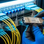
The team selected vendor-matched optics where possible, but they also qualified third-party modules to avoid supply delays. For multimode, they chose 10G SFP+ 850 nm SR modules compatible with OM3/OM4 budgets; for long reach, they chose 10G SFP+ 1310 nm LR modules for single-mode. In practice, the selection emphasized DOM behavior, because the monitoring platform used DOM thresholds to detect degradation early.
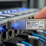
They tested specific models before rollout, including widely deployed enterprise and telecom-compatible parts such as Cisco SFP-10G-SR and Finisar FTLX8571D3BCL for SR-class multimode, and FS.com SFP-10GSR-85-style SR variants where documentation and DOM output matched expected ranges. Exact part compatibility can vary by switch vendor firmware and transceiver qualification; the project therefore used a staged burn-in and a telemetry baseline comparison before any site-wide swap.
Pro Tip: In telecom monitoring systems, the most disruptive failures are not total link drops but “DOM threshold drift” that triggers flapping alerts. During qualification, log DOM values for at least 24 to 72 hours at steady load and verify that vendor-to-vendor differences in reported Tx power and bias current do not cause false positives.
Implementation steps: from lab validation to live cutover
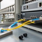
The project followed a disciplined process that field engineers recognize as essential for optical migrations: validate signaling, validate optical budgets, then validate operational behavior under real load. They started with a lab bench using spare patch panels and representative fibers, then moved to a single pilot uplink group per site.
Step-by-step approach used by the team
- Map fiber runs and budgets: measure end-to-end attenuation and confirm connector cleanliness practices; separate OM3/OM4 and OS2 segments.
- Confirm switch support: verify the exact port type (SFP+ vs SFP), optics mode (SR vs LR), and whether the platform requires vendor-specific firmware compatibility.
- DOM and alarm baseline: capture Tx/Rx power, laser bias current, and temperature for each module type; compare to the existing “known good” modules.
- Burn-in with traffic: run sustained line-rate traffic for at least several hours and monitor CRC/FCS errors, link renegotiations, and optical telemetry trends.
- Staged cutover: replace modules in small batches during off-peak windows; maintain a rollback plan with pre-labeled spares.
- Post-cutover verification: validate interface counters, optical thresholds, and monitoring dashboards; confirm no increase in retransmits or microbursts.
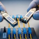
During implementation, they also cleaned all LC connectors using standardized inspection and cleaning procedures. In field deployments, contaminated connectors are a leading cause of excessive attenuation and intermittent receiver loss, especially when modules are swapped frequently during maintenance windows.

Measured results and lessons learned from the migration
Across four aggregation sites, the team replaced SFP+ optics on 48 to 96 uplink ports per site depending on cabinet layout. After cutover, the network team reported stable link state with no persistent alarm storms. CRC errors returned to baseline, and monitoring alerts correlated to real events rather than optics telemetry noise.
Operationally, the biggest improvement was maintenance speed: technicians completed swaps in shorter windows because the DOM telemetry behaved consistently and the monitoring system did not require manual threshold tuning per vendor. In addition, the team reduced mean time to repair by keeping a “fiber type to module type” mapping in the runbooks, which prevented accidental SR/LR mismatches during urgent replacements.
Selection criteria checklist for SFP use cases in telecom networks
Engineers evaluating SFP use cases typically weigh more than reach. Use this ordered checklist to reduce trial-and-error and avoid compatibility surprises.
- Distance and fiber type: confirm OM3/OM4 multimode vs OS2 single-mode; validate connector type and patch loss.
- Data rate and standard: ensure the transceiver matches your Ethernet speed and intended standard (SR or LR class behavior).
- Switch compatibility: confirm the exact SFP+ slot behavior and whether the platform supports third-party optics without err-disable.
- DOM support and thresholds: verify telemetry availability and whether your monitoring platform expects specific DOM ranges.
- Operating temperature: check module spec for 0 to 70 C or extended range; confirm chassis airflow meets requirements.
- Vendor lock-in risk: evaluate supply lead times, firmware qualification policies, and the cost of maintaining multiple transceiver families.
- Return policy and failure handling: prioritize suppliers with clear RMA processes and documented optical compliance.
Common mistakes and troubleshooting tips
Even with correct specifications, field issues happen. Below are common failure modes seen in telecom-like environments, with root causes and practical fixes.
-
Mistake: SR optics installed on the wrong fiber type
Root cause: SR modules (850 nm) used on single-mode runs or wrong patch panels, causing receiver loss and link instability.
Solution: label fibers by wavelength plan; verify with OTDR or attenuation checks; use a pre-cutover fiber verification checklist. -
Mistake: Ignoring connector cleanliness after module swaps
Root cause: LC end faces get micro-scratched or contaminated, increasing attenuation and triggering intermittent Rx failures.
Solution: inspect with a fiber scope before insertion; clean with lint-free wipes and approved cleaning cartridges; re-check optical power. -
Mistake: DOM threshold mismatch leading to false alarms
Root cause: different vendors report DOM values with slightly different calibration offsets; monitoring interprets them as degradation.
Solution: record DOM baselines per module type during qualification; adjust monitoring thresholds with change control, or standardize vendor families. -
Mistake: Overlooking thermal airflow constraints
Root cause: blocked vents or high ambient rack temperatures push module temperature near limits, increasing error rates.
Solution: validate chassis fan profiles; confirm sensor readings stay within module spec; improve cable management for airflow.
Cost and ROI note: balancing optics price, downtime, and TCO
In typical telecom spares planning, SFP optics often cost less per unit than QSFP equivalents, but the total cost depends heavily on operational downtime and failure handling. As a rough field reality, 10G SR SFP+ modules commonly fall in the low tens of USD per unit for third-party options and higher for OEM-branded optics, while LR-class modules usually cost more due to single-mode laser components. The ROI comes from reducing maintenance time and avoiding repeated truck rolls caused by compatibility surprises or telemetry-driven false alarms.
Third-party optics can be cost-effective, but only when qualification data and DOM behavior match your switch and monitoring stack. A practical TCO model includes module price, expected failure rate under your thermal conditions, labor cost per swap, and the cost of monitoring noise that consumes engineer attention.
FAQ: SFP use cases questions engineers ask before buying
What are the most common SFP use cases in telecom networks?
Most deployments use SFP+ for 10GBASE-SR multimode links inside buildings and 10GBASE-LR for longer single-mode runs between cabinets or across floors. They also appear at access and aggregation edges where port density and cost trade-offs favor SFP-class optics over higher-speed pluggables.
How do I choose between SR and LR for a specific run?
Start with measured distance and fiber type. If you have OM3 or OM4 multimode and the run is within spec reach, SR is usually the simpler and lower-cost choice; for OS2 single-mode or longer distances, LR is the safer selection.
Will third-party SFP optics work with my switch?
Sometimes yes, but compatibility depends on the platform’s transceiver qualification behavior and firmware. Always test in a pilot group and validate link stability plus DOM telemetry integration with your monitoring system before scaling.
What DOM checks matter most after installation?
Track Tx power, Rx power, laser bias current, and module temperature for each port. The goal is to confirm stable telemetry trends and ensure your alert thresholds reflect realistic vendor-specific calibration behavior.
Why do I see link flaps even when the fiber type matches?
Common causes include dirty connectors, marginal optical budgets due to patch cord loss, or thermal stress. Inspect connectors, verify attenuation end-to-end, and confirm the chassis airflow keeps module temperatures within spec.
When should QSFP be preferred over SFP?
Prefer QSFP when your switch design offers higher bandwidth per slot and you need to reduce port count for the same throughput. For edge uplinks where speeds are limited to 10G and your chassis already has abundant SFP+ capacity, SFP use cases remain efficient and operationally straightforward.
If you want to extend this approach beyond 10G edges, review QSFP and SFP compatibility for upgrade planning to understand how to coordinate optics families during multi-speed migrations. Next, build a small qualification matrix in your lab so your production cutovers follow predictable optics and monitoring behavior.
Author bio: I have deployed and troubleshot optical transceivers in carrier-grade access and aggregation networks, including DOM telemetry validation and cutover runbooks. My work focuses on measurable link stability, compatibility testing, and operational reliability under constrained thermal and maintenance windows.