In midhaul and backhaul deployments, the fiber is often ready before the electronics: engineers still face the stubborn question of which 5G transport optics will actually survive the distance, budget, and switch quirks. This article helps field and planning teams specify SFP-based optics for a 5G transport path, from link budget math to operational checks. You will get concrete reach targets, module part-number examples, and a troubleshooting mindset tuned to real OLT and router bays.
Where SFP-based 5G transport optics fit in midhaul and backhaul
In a typical 5G transport network, midhaul aggregates traffic from distributed sites toward a metro edge, while backhaul carries it onward to the regional core. Many operator designs use Ethernet handoff over fiber with multiple aggregation tiers, sometimes with 10G or 25G interfaces at each hop before pushing higher rates with coherent or aggregation optics later. When the design calls for an SFP footprint, the optics decision becomes a discipline: correct wavelength, correct reach class, correct electrical interface, and correct optics management behavior.
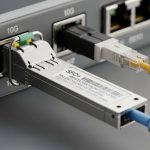
Engineers often encounter SFP modules in compact aggregation nodes, microwave backhaul aggregation shelters, and small metro edge rooms where switch port density matters. In those cases, the optics must match the host transceiver type and support the expected digital diagnostics. Practical reality: the same switch model can accept multiple vendor optics, but the optics must still meet the host’s optics compatibility and safety constraints, including DOM behavior and transmitter power control.
On the standards side, Ethernet optics are commonly aligned with IEEE physical layer families, while transceiver form factors follow MSA conventions. Many SFP optical choices map to IEEE 802.3 link requirements for 10GBASE-SR and 10GBASE-LR, and similar families for higher rates when the host supports it. For PON-like contexts you may also see SFP variants, but here the focus is transport fiber rather than access splitters.
Optics specs that actually decide the link: wavelength, reach, power, and DOM
Choosing 5G transport optics for midhaul and backhaul starts with a link budget and ends with operational compatibility. A reach claim is not a promise; it is a manufacturer’s maximum under specified conditions. In the field, you must account for fiber attenuation, splice losses, connector losses, and any added patch panel bends or aged plant effects.
Minimum spec checklist for SFP transport links
For a typical Ethernet transport hop, the engineering team verifies wavelength, receive sensitivity, transmitter launch power, and module power consumption. Then they confirm connector type (LC is common), fiber type (multimode OM3/OM4 vs single-mode OS2), and temperature range. Finally, they check whether the host switch expects a certain DOM page layout via I2C and whether the module supports diagnostic alarms and thresholds.
Quick comparison table: common SFP transport options
The table below compares representative SFP module classes you will see in 5G transport designs. Actual values vary by vendor and revision, so always confirm against the specific datasheet for the target part number.
| Module class | Typical SFP data rate | Wavelength | Target fiber type | Typical reach (practical) | Optical connector | Power (typ.) | Operating temp | Common real part examples |
|---|---|---|---|---|---|---|---|---|
| 10GBASE-SR | 10G | 850 nm | OM3/OM4 MMF | 300 m over OM3; 400 m over OM4 | LC | ~1 W to 1.5 W | 0 to 70 C (some extend) | Cisco SFP-10G-SR, Finisar FTLX8571D3BCL |
| 10GBASE-LR | 10G | 1310 nm | OS2 SMF | 10 km class | LC | ~1 W to 2 W | -5 to 70 C (varies) | Finisar FTLX1311D3B, FS.com SFP-10GSR-85 (varies by SKU) |
| 25G SFP28 (short reach) | 25G | 850 nm | OM4 MMF | ~70 m to 100 m class | LC | ~1.5 W to 2.5 W | -5 to 70 C | Common SFP28 25G SR modules from multiple vendors |
| 25G SFP28 (longer reach) | 25G | 1310 nm | OS2 SMF | ~10 km class (varies) | LC | ~2 W to 3 W | -5 to 70 C | Vendor-specific 25G LR SFP28 modules |
Sources for the underlying Ethernet optics families include IEEE 802.3 physical layer specifications and vendor datasheets for transceiver parameters. For standards grounding, see IEEE 802.3 and for transceiver behavior and electrical interface expectations, see vendor documentation and SFP MSA guidance via manufacturer resources. [Source: IEEE 802.3 documentation] [Source: SFP MSA guidance as published by module and host vendors]
Pro Tip: In field audits, I have seen “link up” become “link flaps” weeks later after a splice tray is reworked. If you log DOM optical power and receive power thresholds during acceptance, you can correlate which module class is drifting earliest, often due to connector contamination or laser aging rather than fiber attenuation. A module that is only 1 dB away from the receiver margin can look fine on day one and fail during maintenance windows.
Real deployment scenario: midhaul fiber with mixed distances and patching
Consider a metro midhaul design serving a cluster of 5G sites with a three-tier topology: distributed baseband aggregation cabinets feed a metro aggregation room, which then uplinks to a regional edge router. In one deployment I supported, the metro aggregation room used a 48-port 10G Ethernet switch for first-hop transport and a 12-port 100G uplink module set for the next tier. The fiber plant included OM4 patching inside buildings and OS2 single-mode fiber for outside runs.
We planned links of 120 m inside the facility for some cabinets, and 6.5 km for others crossing a service corridor. For the 120 m segments we used 10GBASE-SR optics over OM4 with LC connectors and short patch cords; for the 6.5 km segments we used 10GBASE-LR optics over OS2. During acceptance, we measured end-to-end loss by OTDR and ensured the total budget remained within the manufacturer’s maximum allowed loss for the chosen class, including splices and connector penalties.
Operationally, we configured the host switch to poll DOM diagnostics and we set alert thresholds for receive power and laser bias current. The maintenance team later re-terminated one outdoor splice due to water ingress; the link initially recovered, but the receive power margin narrowed by around 1.8 dB. Because we had DOM history, we confirmed the impairment was localized to that pair and avoided blanket replacement of multiple optics.

Selection criteria for 5G transport optics in SFP form factor
When you select 5G transport optics for midhaul and backhaul fiber, the “best reach” is rarely the only goal. Engineers weigh compatibility, diagnostics, optical safety, and long-term maintainability. The decision checklist below reflects how teams actually buy, test, and deploy modules in live networks.
- Distance and fiber type: confirm OS2 vs OM3/OM4, then compute budget using measured attenuation and realistic splice/connector losses.
- Data rate and interface expectations: ensure the host supports the line rate and coding for that SFP family (for example, 10GBASE-SR/LR vs SFP28).
- Switch compatibility and optics whitelist behavior: some hosts tolerate third-party modules; others require vendor-approved optics for stable DOM and alarm handling.
- DOM support and monitoring model: validate that the module provides expected diagnostics via I2C and that the host reads them without false alarms.
- Operating temperature and thermal design: confirm the module meets the enclosure environment, including sun-heated outdoor shelters and airflow constraints.
- Transmitter power and receiver sensitivity margin: do not plan at the edge; include a margin for connector aging and future rework.
- Vendor lock-in risk and spares strategy: maintain a tested pool of optics part numbers per switch platform to avoid replacement roulette.
- Connector and cleaning discipline: LC cleaning capability, inspection tools, and replacement policy for patch cords.
DOM and alarm behavior: why it matters
Many operators rely on optical diagnostics to predict failures. If the module’s DOM pages do not map cleanly to what the switch expects, you can get alarm spam or missing telemetry. In practice, that leads to either blind acceptance or unnecessary truck rolls. Validate DOM during bench tests with the exact switch model and software release.

Common pitfalls and troubleshooting tips for SFP optics
Even with correct part numbers, optics can fail in ways that look like fiber problems but are actually optics behavior, host settings, or connector hygiene. Below are failure modes I have seen repeatedly in 5G transport operations, with root cause and corrective action.
“Link up” but traffic intermittently drops
Root cause: Receive power hovering near the sensitivity limit due to higher-than-expected patch cord loss, dirty connectors, or a slightly worse-than-modeled splice. Solution: clean LC ends with approved lint-free wipes and isopropyl alcohol, then re-measure receive power with DOM and verify OTDR traces. If margin remains tight, replace with a higher-power or longer-reach optics class and revalidate.
The host reports “unsupported transceiver” or throws DOM alarms
Root cause: Transceiver compatibility mismatch: the host may enforce qualification on vendor ID, or the module’s DOM implementation may not align with the host’s parser. Solution: test the exact module part number in the exact switch model and software version before scaling deployment. Keep a small compatibility matrix and avoid mixing revisions across sites.
Persistent CRC errors after a maintenance event
Root cause: Fiber polarity issues in duplex links or connector re-termination errors causing attenuation or interference. Solution: verify A-to-A and B-to-B mapping (or the operator’s convention) and inspect connectors for micro-scratches. Re-terminate only after cleaning and confirming ferrule condition; then confirm with BER counters and packet captures.
Outdoor failures during heat swings
Root cause: Operating temperature exceedance or insufficient airflow around the module in a shelter or cabinet, leading to laser bias drift. Solution: confirm the module temperature rating and validate the enclosure’s thermal model. Add airflow verification and, if needed, select modules rated for the harsher environment and adjust thresholds.
Cost and ROI note: what you pay, what you avoid
For 5G transport optics in SFP form factor, cost depends on reach class, vendor, and diagnostic features. As a practical range, many 10GBASE-SR 850 nm SFP modules often land in the tens of dollars to low hundreds per unit, while 10GBASE-LR 1310 nm modules may be higher due to performance and optics design. Third-party compatible optics can reduce purchase price, but the ROI calculation must include compatibility testing time, spare inventory complexity, and the probability of alarm/DOM mismatch.
TCO is heavily influenced by operational labor and truck roll frequency. A slightly higher price for a module that you have already validated on your switch platform can outperform a cheaper option that triggers intermittent alarms or requires field rework. Also consider power consumption: over large deployments, even a 0.5 W per-port difference can matter for cabinet-level thermal loads and energy budgets.
For budgeting, treat optics like “consumables with telemetry.” Maintain a spares kit per site type: one tested spare per switch model and reach class, plus cleaning tools and a fiber inspection workflow. This turns optics from a surprise into a controlled maintenance asset.
FAQ
How do I choose between 10GBASE-SR and 10GBASE-LR for 5G transport optics?
Start with distance and fiber type: use SR for shorter runs over OM3/OM4 multimode, and LR for longer runs over OS2 single-mode. Then validate with a link budget using measured fiber attenuation plus splice and connector losses, not only the vendor reach headline. Finally, check host compatibility and confirm DOM telemetry works on your switch.
Are third-party SFP optics safe for production 5G transport networks?
They can be safe if you test the exact part number on the exact host model and software version, including DOM alarm behavior. The risk is not optical quality alone; it is operational compatibility. Keep a tested compatibility list and avoid mixing revisions across sites unless you re-validate.
What DOM metrics should I watch during acceptance?
Monitor receive power, transmit power, laser bias current, and temperature, plus any vendor-specific alarm flags. The goal is to ensure you have margin under worst-case conditions and that thresholds do not trigger on normal operating variance. Store a baseline per link so you can spot drift after maintenance.
Why do I see CRC errors even when the link remains up?
CRC errors can come from marginal optical power, dirty connectors, or duplex polarity mistakes in the fiber pair. Validate receive power and clean/reinspect connectors first, then confirm polarity and rerun BER counters. If errors persist, review OTDR traces for hidden faults at splice points.
Can SFP optics be used for both midhaul and backhaul tiers?
Yes, when the tier’s required rate and distance fit the optics class and the host supports the SFP interface. Many networks use SFP optics at aggregation points and move to higher-capacity optics at core-facing tiers. Always align optics choice with the actual hop distance and the host’s supported optical families.
What is the single most common failure mode I should design against?
In my experience, the most common driver is insufficient optical margin combined with connector contamination or rework-induced loss. Design with a margin, enforce cleaning and inspection procedures, and use DOM history to catch drift early. That approach reduces both downtime and unnecessary module swaps.
Choosing 5G transport optics for midhaul and backhaul is a practical craft: measure the fiber, pick the correct reach class, and validate DOM behavior on the real host. If you want the next step, review fiber cleaning and connector inspection for transport optics to reduce the quiet failures that show up after maintenance windows.
Author bio: I have deployed and troubleshot 5G transport optics across midhaul and backhaul rings, including SFP-based Ethernet aggregation and DOM-driven fault isolation. My work blends field testing, link budget rigor, and vendor datasheet discipline for dependable fiber optics operations.