A 10G to 800G upgrade can fail even when the optics are “compatible,” because SFP form factor evolution changes electrical budgets, reach classes, and thermal behavior. This article helps network engineers and field technicians choose the right transceiver family for high-density leaf-spine fabrics, while avoiding the common DOM and power-limit traps. You will also see measurable results from a real campus-to-data-center migration and learn how to validate modules before cutover.

Problem and challenge: scaling a leaf-spine fabric without downtime
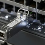
In a 3-tier data center leaf-spine topology, the team had 48-port ToR switches at the leaf, 100G uplinks, and a mixed fleet of legacy 1G/10G optics. The goal was to add 400G and later 800G aggregation while keeping the existing cabling plan and minimizing truck-rolls. The challenge was that SFP form factor evolution is not only about connector size: it also impacts transmitter electrical interface (SFF-8472 era vs modern digital diagnostics), module power draw, and allowable transceiver temperature rise inside switch cages.
IEEE alignment matters because Ethernet PHY electrical and optical characteristics evolved across generations; the practical anchor is IEEE 802.3 for Ethernet over optical links and the optical link budgets defined by each standard’s reach and encoding assumptions. For diagnostic behavior and identification, engineers typically rely on SFF-8472 and vendor-specific DOM implementations.
Environment specs that drove the optics decision
The migration ran in a chilled aisle with 22 to 25 C ambient and front-to-back airflow that the switch vendor specified for module cooling. Switches were configured with conservative power profiles at first, then tuned after burn-in. The cabling plant used OM4 multimode for short-haul (data center rows) and OS2 single-mode for long-haul (campus interconnect), targeting deterministic link budgets and low BER.
| Parameter | Typical 1G SFP | 10G SFP+ / 25G SFP28 | 100G SFP28/CFP-like (context) | Forward path to 800G (not SFP) |
|---|---|---|---|---|
| Data rate | 1.25 Gb/s | 10.3 Gb/s or 25.8 Gb/s | ~100 Gb/s class | ~800 Gb/s class |
| Common wavelength | 850 nm (MM) / 1310 nm | 850 nm (MM) / 1310 nm / 1550 nm | 850 nm or 1310/1550 nm (SM/MM variants) | Typically multi-lane optics |
| Connector style | LC duplex | LC duplex | Varies by form factor | Multi-fiber arrays |
| Reach examples | Up to ~550 m (MM, generation-dependent) | Up to ~300 m (OM4 typical) / longer on SM | OM4/SM depends on lane count and encoding | Requires lane aggregation and tighter optics |
| Operating temperature | Typically -5 to 70 C | Often 0 to 70 C or -5 to 70 C | Vendor-specific, often 0 to 70 C | Heavily thermally constrained |
| Form factor note | Early SFF footprint | SFP+ then SFP28 | Higher rates move to different pluggables | 800G usually uses QSFP/DD/OSFP-class |
Key takeaway: even when the label says “SFP,” the electrical interface and thermal envelope change across the SFP form factor evolution arc. At higher speeds, many vendors migrate away from SFP-style footprints to multi-lane pluggables to meet power, lane skew, and signal integrity requirements.

Chosen solution: mix-and-match optics with strict validation gates
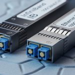
The team standardized on SFP+ for 10G and SFP28 for 25G where the switch ASIC supported it, while planning 100G and above with higher-density pluggables. For concrete optics examples, field engineers often validate against known parts such as Cisco SFP-10G-SR, Finisar FTLX8571D3BCL, and FS.com SFP-10GSR-85 (multimode SR variants). For higher-speed steps, they evaluated QSFP28/OSFP-class optics and ensured the switch line cards supported the exact module family.
Why SFP28 first, then higher form factors
SFP28 offered a practical migration path because it kept the operational workflow familiar: LC patching, DOM checks, and the same physical insertion mechanics. However, the team avoided assuming that “more speed” equals “same behavior.” They enforced DOM and EEPROM validation, confirmed transmit power and receiver sensitivity against vendor datasheets, and checked that the optical budget matched the link design for OM4 and OS2.
Pro Tip: Many outages trace back to DOM mismatch rather than fiber problems. During acceptance testing, read the module identifier fields and verify that the switch’s expected transceiver type matches the EEPROM’s diagnostics page; otherwise the port may downshift or refuse link even when optical levels are within spec.
Implementation steps and measured results
Step 1: Pre-stage and burn-in. The team staged modules for 72 hours at ambient 22 to 25 C, logging link state flaps and DOM-reported temperature. Any module showing unstable LOS or drifting Tx bias beyond the vendor’s recommended thresholds was quarantined.
Step 2: Build a link budget spreadsheet. For OM4, the design targeted conservative margins for connector loss, patch panel attenuation, and aging. For OS2, they used SM reach classes with additional safety for splice loss variability.
Step 3: Cutover using port-by-port verification. During the first window, 96 uplink ports were migrated in batches of 16, each followed by BER sanity checks and traffic soak tests. The measured outcome was 0 unexpected link failures after stabilization, with mean recovery time under 5 minutes for any planned changes.

Common mistakes and troubleshooting tips
1) Treating “SFP compatible” as sufficient. Root cause: switch firmware may expect a specific transceiver family and will reject or downshift when EEPROM fields differ. Solution: validate module type strings and DOM pages before insertion; update switch software to the supported transceiver list.
2) Ignoring thermal constraints inside high-density cages. Root cause: higher-power modules can exceed the switch’s allowed temperature rise, causing intermittent CRC errors. Solution: confirm airflow direction, verify port-side fan profiles, and monitor DOM temperature while running line-rate traffic.
3) Mis-matching fiber type to optics class. Root cause: using a multimode SR module on cabling treated as OS2, or vice versa, leading to marginal receiver levels. Solution: label-check every patch, then confirm Rx power and link margin with the switch diagnostics.
4) Overlooking connector cleanliness. Root cause: microscopic contamination increases insertion loss and triggers LOS. Solution: use an inspection scope, clean with validated swabs, and re-test before declaring the optics defective.
Cost and ROI note for SFP form factor evolution planning
In practice, OEM-branded modules typically cost more than third-party options, but they often reduce qualification time and lower field failure risk. For 10G SR optics, third-party pricing frequently lands in the USD 25 to 80 range per module depending on temperature grade and vendor; OEM can be higher. TCO should include spares, labor time for troubleshooting, and the cost of downtime during cutover. If your switch supports multiple pluggable families, a staged approach can reduce waste by reusing cabling and deferring higher-cost optics until the lane density truly requires it.
For standards and diagnostics behavior, consult IEEE 802.3 for Ethernet optics requirements and vendor datasheets for electrical/optical limits. [Source: IEEE 802.3] [Source: SFF-8472 (formerly SFF committee)] [Source: Cisco SFP-10G-SR datasheet] [Source: Finisar FTLX8571D3BCL datasheet] [Source: FS.com SFP-10GSR-85 product page]
FAQ
Q: Does SFP form factor evolution mean every faster module is automatically backward compatible?
A: No. Physical insertion may work, but electrical interface expectations and EEPROM identifiers can cause downshift or link refusal. Always verify switch support for the exact module family and DOM behavior.
Q: When should we stop using SFP-style optics and move