In an SDN fabric, a single wrong optical transceiver choice can cause link flaps, degraded latency, or expensive truck rolls. This article helps network and field engineers select an SDN optical transceiver by mapping SDN control expectations to physical-layer realities: reach budgets, optical wavelengths, power classes, temperature limits, and diagnostics. You will get practical selection criteria, a specs comparison table, troubleshooting patterns, and ROI guidance for both OEM and third-party optics. Update date: 2026-04-30.
How SDN changes optical transceiver selection
Software-defined networking pushes configuration and intent through controllers, but the photonic layer still enforces hard physics. In practice, SDN expects the transceiver to match the switch port electrical standards (for example, 10GBASE-SR over SFP+), support deterministic link behavior, and expose diagnostics so automation can validate health. Many SDN platforms also rely on DOM (Digital Optical Monitoring) fields to trigger remediation workflows when optical power drifts or error counts rise.
At the same time, SDN introduces faster change cycles: controllers may deploy new paths within minutes, so optics must tolerate repeated enable/disable events and cold-start conditions without marginal links. Field engineers commonly see problems when automation assumes “link up means good” while the transceiver is actually operating near its receiver sensitivity threshold due to fiber aging, patch cord loss, or a connector geometry mismatch. The solution is to treat transceiver selection as part of an end-to-end link budget, not a checkbox on a switch compatibility list.
Key optical specs that decide whether SDN links stay stable
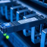
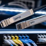
Start with the optical interface type and then validate that your physical plant supports it across temperature and aging. The most common SDN scenarios use Ethernet optics defined by IEEE 802.3 (for example, 10GBASE-SR and 100GBASE-SR4). You then translate SDN intents (reach, redundancy, and failure domain boundaries) into a link budget that includes transmitter power, receiver sensitivity, fiber attenuation, connector loss, and margin for worst-case conditions.
| Spec / Parameter | 10GBASE-SR (SFP+) | 100GBASE-SR4 (QSFP28) | 40/100G LR4 (QSFP+/QSFP28) |
|---|---|---|---|
| Typical wavelength | 850 nm | 850 nm (4 lanes) | ~1310 nm (4 lanes) |
| Nominal reach (spec) | Up to 300 m over OM3/OM4 | Up to 100 m over OM4 (varies by vendor) | Up to 10 km (depends on class) |
| Connector type | LC | LC (MPO/MTP to LC breakout) | LC |
| Diagnostic support | DOM via I2C (vendor-specific) | DOM typically includes lane power and bias | DOM typically includes Tx bias, Rx power, temperature |
| Operating temperature | Commonly 0 to 70 C (commercial) or wider options | Commonly 0 to 70 C | May offer extended ranges for metro shelters |
| Power class / safety | Class 1 laser product; verify datasheet | Class 1 laser product; verify datasheet | Class 1 laser product; verify datasheet |
When you run SDN automation, you want the transceiver to provide consistent DOM thresholds so your controller can decide whether a path is “healthy enough” to place traffic. For example, if the switch reports Tx bias current trending upward while Rx power trends downward, SDN can preemptively migrate traffic rather than waiting for hard link loss. This is especially important in multi-tenant data centers where fiber moves and patching happen frequently.

Selection checklist for SDN optical transceivers (engineer-ready)
The best way to avoid SDN instability is to follow a repeatable checklist that ties optics to measured fiber characteristics and switch behavior. Use this ordered sequence during procurement and before staging optics for automation.
- Distance and fiber type: Confirm OM3 vs OM4 vs single-mode, then compute worst-case attenuation using measured values (for example, dB per connector plus patch cords). Do not rely on “rated” cable lengths alone.
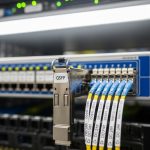
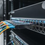
- Switch port and electrical standard compatibility: Validate the transceiver format (SFP+, QSFP28, QSFP) and the Ethernet standard expected by the switch vendor firmware. Check for known compatibility quirks with specific switch models and optics revisions.
- Wavelength and lane mapping: For multi-lane optics (SR4, LR4), verify MPO polarity handling and correct lane mapping. A polarity error can create systematic BER issues that still show “link up.”
- Link budget margin: Use vendor datasheets for Tx power and Rx sensitivity, then include connector loss and aging margin. Aim for a conservative margin so DOM thresholds remain comfortably inside limits over the service life.
- DOM and automation hooks: Ensure the optic supports the DOM fields your SDN tooling monitors (Tx power, Rx power, temperature). Confirm your collector can read I2C/EEPROM values without permission or polling-rate issues.
- Operating temperature and airflow profile: Measure the actual module temperature in your rack. If the site has limited airflow, choose optics with appropriate temperature ratings and verify that the switch port does not exceed thermal constraints.
- Vendor lock-in risk and procurement strategy: Compare OEM vs third-party availability, lead times, and firmware compatibility. If you use third-party optics, validate them in a pilot with your exact switch models.
- Lifecycle and RMA practicality: Check warranty terms, expected failure modes, and whether the vendor provides batch-level traceability (serial number mapping to manufacturing date).
Pro Tip: In SDN environments, treat DOM not just as “monitoring,” but as an input to orchestration. If you set automation thresholds based on observed Rx power and temperature drift rather than waiting for link-down events, you can reduce traffic disruptions caused by optics operating near sensitivity limits.
Deployment scenario: leaf-spine SDN with 10G and 100G optics
Consider a 3-tier data center leaf-spine topology with 48-port 10G ToR switches at the leaf and 100G spine uplinks. Suppose each leaf has 24 active 10G server connections and 4 uplinks at 10G to an aggregation tier, while the spine uses 100G links between tiers. In one rollout, the operations team standardized on 10GBASE-SR SFP+ for top-of-rack to aggregation within the same row, and 100GBASE-SR4 QSFP28 for short-reach spine uplinks across a structured cabling zone.
During commissioning, the team measured OM4 patch cord attenuation and connector loss, then confirmed that the selected optics met a link budget that preserved margin under worst-case temperature. They also enabled DOM polling every 30 seconds and correlated Rx power trends with interface error counters. When a subset of ports began showing rising error rates without link-down, the root cause was a batch of patch cords with higher-than-documented insertion loss; replacing cables restored stable BER behavior. This is the SDN advantage: faster detection and path adjustment, but only if the optics provide reliable diagnostics.

Common pitfalls and troubleshooting patterns
Even experienced teams run into repeatable failure modes. Below are concrete mistakes, their likely root causes, and what to do next.
“Link up” but traffic quality degrades (high BER)
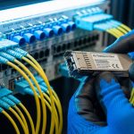
Root cause: MPO polarity mismatch on SR4/LR4 multi-lane optics, or incorrect lane mapping during patching. Another cause is operating near sensitivity due to excessive patch cord loss. Solution: Verify MPO polarity using a polarity testing procedure, re-seat fibers carefully, and compare DOM Rx power values against vendor guidance. Replace suspect patch cords and re-run interface counters and BER/CRC error checks.
Intermittent link flaps after automation changes
Root cause: Thermal stress during rapid port toggling, insufficient airflow, or optics with marginal temperature ratings for the rack environment. Some optics also exhibit startup latency variance that interacts with switch port state machines. Solution: Measure module temperature and confirm thermal airflow. Stagger port bring-up during maintenance windows and validate that your switch firmware supports the optics’ timing behavior.
DOM fields missing or inconsistent in orchestration workflows
Root cause: Third-party optics that implement DOM differently, EEPROM read timing differences, or monitoring software polling too aggressively and hitting bus contention. Solution: Confirm DOM support by reading key I2C/EEPROM fields at boot, then tune polling intervals. In pilots, record DOM field behavior across a full temperature range and during link resets.
Compatibility surprises between switch revisions
Root cause: Firmware updates can change how the switch validates optics (EEPROM content checks, thresholds, or supported diagnostic pages). Solution: Maintain a compatibility matrix by switch model and firmware version, and re-validate optics after upgrades. For SDN, consider canary deployments where only a small set of links use a new optic revision.
Cost, TCO, and ROI for OEM versus third-party optics
Optics pricing varies by reach class, speed, and diagnostic feature set. As a practical range, engineers often see 10G SR SFP+ optics in the tens to low hundreds of USD per unit depending on OEM vs third-party and warranty terms, while 100G SR4 QSFP28 can cost several times more. Third-party optics may reduce unit price, but they can increase operational cost if DOM behavior or switch compatibility requires extra validation, or if replacement cycles are more frequent.
For SDN TCO, include not just purchase price but also engineering time for onboarding, the risk of automation false positives, and the cost of downtime during fiber patch events. In many environments, the ROI of OEM optics comes from predictable compatibility and consistent DOM, which reduces troubleshooting time. However, third-party optics can still make sense when you run a disciplined pilot, lock compatibility by switch firmware, and maintain clear RMA and traceability processes.

FAQ
What makes an SDN optical transceiver different from a normal data center optic?
The optics are physically similar, but SDN places higher emphasis on telemetry quality and automation behavior. You typically need consistent DOM fields, predictable startup and link state transitions, and stable performance under orchestration-driven changes. That is why compatibility testing and telemetry validation matter more in SDN than in static networks.
Which standards should I check when selecting an SDN optical transceiver?
For Ethernet over fiber, start with IEEE 802.3 specifications relevant to your speed and reach class, such as 10GBASE-SR and 100GBASE-SR4. Then confirm the switch vendor requirements in their optics compatibility documentation. Finally, verify the optic datasheet for wavelength, reach, DOM features, and temperature range.
How do I validate link budget before deployment?
Use vendor datasheet values for transmitter power and receiver sensitivity, then add measured fiber attenuation and connector/patch cord losses. Include worst-case margins for aging and temperature. If possible, measure receive power using an optical power meter and compare it to expected DOM ranges.
Can I mix OEM and third-party optics in the same SDN fabric?
You can, but you should validate compatibility per switch model and firmware version. Mixing optics can lead to differences in DOM scaling, threshold behavior, or startup timing. A safe approach is to run a pilot on a small set of ports and ensure your SDN monitoring logic interprets telemetry correctly across vendors.
What are the fastest troubleshooting steps when SDN reports link instability?
First, check interface counters and whether the link flaps correlate with temperature or optics telemetry drift. Next, confirm fiber polarity and patch cord types, especially for SR4/LR4 multi-lane optics. Finally, compare DOM Tx bias and Rx power against vendor guidance and replace the smallest suspect component (patch cord or optic) in a controlled test.
Do I need DOM support for SDN automation?
Many SDN workflows become significantly more effective with DOM because you can trigger remediation based on optical health rather than waiting for link-down. If your SDN controller integrates telemetry, you should ensure the optic provides the specific DOM fields and that polling rate does not overload the switch management bus.
If you want a practical next step, build a small test matrix with your exact switch models and firmware, then validate reach and DOM behavior under realistic patch cord loss. After that, standardize procurement and document compatibility so SDN automation can scale safely using consistent optical telemetry.
Related topic: How to build a fiber link budget for data center optics
Author bio: I’m a network engineer who has deployed SDN fabrics in multi-rack data centers, focusing on optics telemetry, link budgets, and field troubleshooting. I write with operator-level details so teams can reduce outages and speed up onboarding.