Ruggedized Ethernet Transceiver Selection for Factory Links
In factory floors, a single link failure can halt a production line, and the wrong optics can quietly erode performance. This article helps industrial engineers and field techs choose a ruggedized ethernet transceiver that matches IEEE 802.3 link requirements, environmental constraints, and switch behavior. You will get practical distance checks, compatibility criteria, troubleshooting patterns, and a cost-aware decision checklist.
Industrial reality: what IEEE 802.3-2018 expects from transceivers
IEEE 802.3-2018 defines Ethernet PHY behavior, optical interfaces, and link characteristics used to build reliable industrial networks. In practice, a ruggedized ethernet transceiver must satisfy the electrical and optical parameters your switch expects: modulation and receiver sensitivity, lane/signal timing, and link negotiation behavior. For fiber-based links, compliance is typically validated against vendor datasheets that reference the IEEE definitions, then verified in lab and field testing.
When you design for industrial Ethernet, remember that “works on the bench” is not the same as “survives on a vibrating conveyor.” You are balancing optical budget, thermal cycling, connector retention, and EMI/ESD tolerance. A ruggedized module usually adds mechanical reinforcement, tighter tolerances, and enhanced environmental ratings, but it still depends on the switch’s optics compatibility and firmware quirks.
Optical budget math you can use in the field
For multimode fiber, a common deployment is 10G over OM4 using SR optics. You still need to account for connector losses, patch cords, and splices, because the link margin shrinks fast in real cable trays. I typically start by estimating total loss: fiber attenuation + connector loss + splice loss + safety margin. Then verify that the transceiver’s stated reach (for example, SR at a given fiber type) exceeds your measured or estimated total.
For single-mode, the math is more forgiving for distance but sensitive to bad termination and dirty connectors. A ruggedized ethernet transceiver will not compensate for optical contamination; it only makes the hardware more survivable while you maintain the link.

Key specifications that decide whether the link holds under stress
Engineers often compare reach and wavelength first, but industrial failures are frequently caused by power, temperature, or connector mechanics. A ruggedized ethernet transceiver selection should explicitly match: data rate, fiber type, wavelength, optical power class, connector style, and the module’s operating temperature range. Also check DOM (Digital Optical Monitoring) support, because maintenance workflows and alarms depend on it.
| Spec (what to verify) | Typical Industrial Choice | Why it matters |
|---|---|---|
| Data rate | 1G/10G/25G/40G depending on switch | Mismatched PHY speed leads to link down or forced fallback |
| Wavelength | 850 nm for SR multimode; 1310/1550 nm for LR/ER single-mode | Determines which fiber plant and transceiver family you can use |
| Reach | SR: OM3/OM4 dependent; LR: single-mode dependent | Must cover patch cords, splices, and aging margin |
| Connector | LC duplex common for fiber | Field vibration punishes loose or poorly retained connectors |
| Operating temperature | Often -40 to 85 C or wider for industrial | Thermal drift affects laser output and receiver sensitivity |
| DOM/diagnostics | DOM supported or not (vendor-dependent) | Enables alarms for TX power, RX power, and module health |
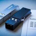
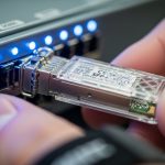
Concrete module examples you might encounter
In real builds, you will see SR optics such as Cisco-branded or compatible 10G SR modules, plus third-party equivalents. Examples include Cisco SFP-10G-SR and Finisar FTLX8571D3BCL, as well as FS.com SFP-10GSR-85 for multimode 850 nm use cases. Always confirm the exact part number matches your switch’s supported optics list and that the DOM behavior aligns with your monitoring tooling.
For copper ruggedization, the story differs: RJ45 modules and cables need robust strain relief and EMI-aware installation. Still, the same diligence applies: link budget is replaced by signal integrity constraints, and connector quality becomes the main failure driver.

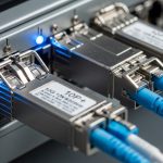
Deployment scenario: choosing ruggedized optics in a leaf-spine factory
Consider a 3-tier data center leaf-spine topology adapted for a factory: 48-port 10G ToR switches at machine rows, aggregating to 2 spine switches in a central IDF. Suppose each machine row has 12 fiber runs averaging 120 m of OM4 with patch cords totaling 10 m per run and two splices. If your SR reach is rated for OM4 at 300 m under ideal conditions, you still subtract real losses: typical connector and splice losses can reduce margin enough that aging and dirty connectors matter.
I have deployed this layout with ruggedized ethernet transceiver modules in enclosures rated for dust and temperature swings, where the key operational requirement was stable DOM telemetry for early warning. In monitoring, we alert on TX power drift and RX power margin thresholds rather than waiting for link down events. When a run later degraded due to a connector that was bumped during maintenance, the alarm triggered before the production line experienced full outage.
Compatibility was verified during commissioning: the switch’s optics compatibility matrix was checked, and each module’s DOM fields were validated so SNMP polling did not return nulls. That step is often skipped, but it is the difference between “we installed it” and “we can operate it safely.”
Selection checklist engineers actually use in commissioning
Use this ordered checklist to select a ruggedized ethernet transceiver that behaves predictably. I recommend treating optics as a controlled component with test acceptance criteria, not as a commodity.
- Distance vs. optical budget: verify reach for your fiber type (OM3/OM4, single-mode) and include connector/splice losses plus a safety margin.
- Switch compatibility: confirm the exact module type is supported by the switch model and software revision; validate speed settings and any required breakout modes.
- DOM and diagnostics: ensure DOM support matches your monitoring stack (alerts, telemetry polling, and thresholds).
- Operating temperature: check the module’s rated range and whether it exceeds your measured enclosure temperature under worst-case duty cycles.
- Connector robustness: prefer LC duplex with consistent latch retention; plan for cleaning access and strain relief.
- Vendor lock-in risk: weigh OEM modules vs third-party; evaluate warranty terms and whether optics are interchangeable without calibration issues.
- Environmental packaging: confirm the ruggedized housing design targets vibration, dust ingress, and cable pull forces typical of your plant.
Pro Tip: In factories, optical failures often start as “telemetry drift,” not as a sudden link-down. If your ruggedized ethernet transceiver supports DOM, set alerts on TX/RX power thresholds and watch for gradual degradation caused by connector contamination or micro-movement in cable trays.
Common mistakes and troubleshooting patterns
Industrial link problems are rarely mysterious; they are usually traceable to repeatable root causes. Below are failure modes I have seen during field acceptance and ongoing operations.
Link down due to wrong fiber type or wavelength mismatch
Root cause: using SR optics on the wrong fiber plant (for example, expecting OM4 performance on a mixed/aged OM3 run) or selecting an incompatible wavelength for the cable plant. Solution: verify fiber type at the patch panel, measure attenuation if uncertain, and validate the transceiver family against the switch’s optics list.
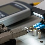
Intermittent flaps caused by connector contamination or vibration
Root cause: dirty LC ends or insufficient strain relief causing micro-movement, which changes coupling efficiency. Solution: clean with proper fiber cleaning tools, inspect with an optical scope, and secure patch cords with vibration-rated clips and correct bend radius.
“It works but monitoring is blind” due to DOM incompatibility
Root cause: selecting a third-party ruggedized ethernet transceiver that does not implement DOM fields the way your switch expects, or your telemetry system assumes a different format. Solution: test DOM reads during commissioning, confirm alert thresholds, and document which fields are populated for each module type.
Thermal-induced degradation in hot enclosures
Root cause: installing modules rated for -40 to 85 C into an enclosure that routinely exceeds the effective operating temperature due to poor airflow or blocked ventilation. Solution: measure enclosure air temperature under load, ensure airflow clearance, and consider higher-rated industrial optics if needed.
Cost and ROI: balancing OEM reliability with lifecycle economics
Pricing varies by data rate and reach, but in many procurement environments you will see OEM ruggedized ethernet transceiver optics priced higher than third-party equivalents. A realistic budgeting range for 10G SR SFP+ optics often falls in the tens of dollars for third-party and higher for OEM, while higher-speed modules (25G/40G) can push into substantially higher tiers depending on wavelength and reach. TCO matters: include cleaning supplies, spares inventory, downtime cost, and warranty handling.
OEM modules can reduce commissioning time when they align closely with switch compatibility and DOM behavior, which lowers labor risk. Third-party modules can be cost-effective, but you must run acceptance tests for link stability, temperature performance, and DOM telemetry completeness to avoid hidden operational costs later.
FAQ
Q: What makes a transceiver “ruggedized” for factory use?
Ruggedized typically refers to enhanced mechanical design for vibration and insertion retention, plus environmental ratings for temperature and dust. It does not change the Ethernet PHY standard itself, so you still must match data rate and optics type to the switch and fiber plant.
Q: Can I mix transceiver brands in the same switch?
Sometimes yes, but not always. Even when optical specs match, DOM telemetry fields and switch compatibility can differ by vendor and firmware revision, so validate with your exact switch model and software.
Q: How do I confirm optical reach beyond the datasheet?
Use optical budget calculations and, ideally, verify with field measurements of link attenuation and connector quality. Include patch cord lengths, splice counts, and aging margin rather than assuming “rated reach” equals “installed reach.”
Q: Do I really need DOM support?
For industrial uptime, DOM is often worth it because it enables early detection of TX power drift, connector issues, and receiver margin changes. If your monitoring stack cannot read DOM reliably, you may lose preventative visibility.
Q: What is the fastest troubleshooting path when links flap?
Start with connector inspection and cleaning, then check for mismatched fiber type or wavelength, and finally validate temperature and airflow conditions. If DOM is available, use TX/RX trends to pinpoint whether the issue is optical coupling, power drift, or environmental stress.
Q: Are IEEE 802.3-2018 standards enough to guarantee compatibility?
They define PHY behavior, but real compatibility depends on vendor implementations, switch optics support lists, and diagnostics behavior. Follow the switch vendor guidance and confirm in commissioning tests.
Ruggedized ethernet transceiver selection is an engineering problem: match IEEE Ethernet behavior to optics, then verify mechanical and environmental realities with commissioning tests and monitoring. Next step: review your switch optics support list and build a short acceptance test plan using DOM telemetry and connector inspection before mass installation. industrial fiber transceiver installation checklist
Author bio: I am a field-deployed network photographer and systems writer who has commissioned industrial Ethernet links in harsh plants, including optics verification with scope-based connector inspection. I document what actually works: mechanical retention, thermal margins, and telemetry-driven troubleshooting.
Update date: 2026-04-30