Renewable energy sites such as wind farms, solar plants, and battery microgrids increasingly depend on deterministic, low-latency networking for SCADA, forecasting, and fleet control. This article helps field and network engineers choose fiber transceivers and cabling that minimize downtime risk, reduce physical footprint, and remain reliable under harsh outdoor conditions. You will get practical selection criteria, specification comparisons, and troubleshooting steps grounded in IEEE Ethernet optical standards and vendor datasheets.
Why renewable energy sites stress fiber optics differently
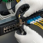
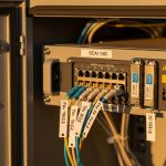
Unlike indoor enterprise closets, renewable energy installations face temperature swings, lightning-induced transients, vibration, and dust ingress. Fiber links typically outperform copper in electromagnetic immunity, but the transceiver itself must tolerate the same environment as the enclosure and cable plant. For Ethernet transport, the optical interface must match the switch or media converter transceiver expectations under IEEE 802.3 (for example 10GBASE-SR or 25GBASE-SR variants) and the vendor’s digital optics requirements (such as DOM availability). In practice, engineers target stable link budgets and consistent optical power margins, not just headline reach.
Operational targets engineers commonly set on site
Field teams often design for a conservative link budget margin of 3 to 6 dB beyond the minimum receiver sensitivity, accounting for connector aging, patch panel losses, and temperature-related drift. For outdoor runs, they also plan for water-shedding hardware and strain relief to prevent micro-bends that can degrade multimode performance. If you are integrating into a leaf-spine topology at a regional control center, you may need deterministic handoff from the site gateway to 10G or 25G uplinks while keeping transceiver power draw manageable across dozens of feeders.

Transceiver choices that reduce installation and failure impact
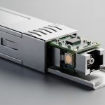
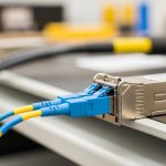
The “low-impact” goal is often about minimizing truck rolls and simplifying field swaps, not only about optical physics. For renewable energy networking, engineers typically choose short-reach multimode for intra-site backbone where run lengths are moderate, and single-mode when you must span across buildings, fence lines, or long cable trays. The correct option depends on distance, fiber type, and the transceiver compatibility requirements of the switching platform. Using optics with robust Digital Optical Monitoring (DOM) can also reduce mean time to repair by making optical power and receive levels visible.
Key specification table for common Ethernet short-reach optics
Below is a practical comparison of widely deployed optics for renewable energy site backhauls and on-site aggregation. Always verify exact compliance with your switch model and optics vendor, since some platforms require specific firmware or DOM behavior.
| Optics class | Typical data rate | Wavelength | Fiber type | Nominal reach | Connector | DOM | Operating temperature (typ.) | Common form factor |
|---|---|---|---|---|---|---|---|---|
| 10GBASE-SR | 10G | 850 nm | OM3/OM4 multimode | 300 m (OM3) / 400 m (OM4) | LC | Often supported | -10 to 70 C (vendor-dependent) | SFP+ |
| 25GBASE-SR | 25G | 850 nm | OM4 multimode | 70 m (common) to 100 m (depends on vendor) | LC | Often supported | -10 to 70 C (vendor-dependent) | SFP28 |
| 10GBASE-LR | 10G | 1310 nm | Single-mode | 10 km (typical) | LC | Often supported | -40 to 85 C (some models) | SFP+ |
| 100GBASE-SR4 | 100G | 850 nm | OM4 multimode | 100 m (typical) | MT/MPO-12 | Often supported | -5 to 70 C (vendor-dependent) | QSFP28 |
For renewable energy sites, the “best” choice is often the one that matches your existing fiber plant and temperature envelope. If your control cabinets can exceed 60 C in summer sun, you should select optics explicitly rated for the deployment temperature range rather than assuming standard commercial optics will survive.
Examples of commonly referenced part families
Engineers frequently start from their switch vendor’s approved optics list, then validate reach and power margins with DOM readings. For instance, 10GBASE-SR optics such as Cisco SFP-10G-SR and compatible Finisar FTLX8571D3BCL-like families are often used in data center and campus contexts, while FS.com SFP-10GSR-85 is a representative third-party 850 nm 10GBASE-SR option. For single-mode LR, you will typically look for 1310 nm SFP+ optics with extended temperature variants when outdoor cabinets are not climate controlled. Always confirm DOM behavior and any vendor-specific alarm thresholds.
Authority notes: IEEE Ethernet optical definitions appear in IEEE 802.3, and detailed power and receiver requirements are specified by the relevant 10G/25G/100G media standards. See IEEE 802.3 standards portal. For DOM expectations, consult switch and optics datasheets from vendors and integrators; DOM is not universally identical across suppliers.
Pro Tip: In the field, “it links today” is not enough. Capture DOM snapshots during commissioning and during peak heat conditions, then set alert thresholds on receive power and bias current so you detect gradual degradation from connector contamination or micro-bends before a full link drop.
Distance, fiber plant, and compatibility: the selection checklist
Selection for renewable energy networking is a multi-constraint optimization. Engineers weigh optical reach and link budget against switch compatibility, temperature rating, and operational supportability. The goal is to avoid a situation where the optics work only under lab conditions but fail during outdoor thermal cycling or after a connector rework.
- Distance and fiber type: Determine whether you have OM3, OM4, or single-mode fiber, then map required reach to the optics class (SR vs LR).
- Link budget margin: Use vendor receiver sensitivity and transmitter power, then include connector and splice losses plus an aging margin.
- Switch compatibility: Verify the transceiver is supported by your switch model and software version (approved optics list where available).
- DOM support and alarms: Confirm DOM fields and thresholds are readable and that your monitoring stack can alert on abnormal receive power.
- Operating temperature and enclosure thermal design: Match optics temperature rating to measured cabinet temperatures at the hottest point in summer.
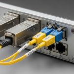
- Connector and patch panel constraints: Confirm LC vs MPO/MTP usage, polarity requirements for MPO, and available cleaning tooling.
- Vendor lock-in risk: Evaluate OEM vs third-party optics total cost of ownership, including replacement availability and support policies.
Common mistakes and troubleshooting steps on renewable sites
Most link failures in renewable energy environments are not “mysterious”; they come from predictable mechanical, optical, or configuration issues. Below are frequent pitfalls seen during commissioning and maintenance, with root causes and corrective actions.
Pitfall 1: Working in the shop, failing outdoors
Root cause: Optics or patch hardware rated for indoor temperatures are installed into unconditioned cabinets that exceed their operational limits. Thermal cycling can also worsen micro-bend stress in tight cable routing.
Solution: Measure enclosure temperatures under peak sun, then select transceivers with appropriate temperature ratings and revise cable routing to reduce bend radius violations.
Pitfall 2: Link flaps after connector rework
Root cause: Contamination on LC endfaces or improper cleaning between swaps causes increased insertion loss and unstable received power. Even a brief contact can leave residue.
Solution: Use lint-free wipes and approved inspection/cleaning tools, verify endface cleanliness under a microscope, and re-terminate if contamination persists.
Pitfall 3: DOM readings look “normal” but traffic fails
Root cause: Monitoring may not capture the specific impairment causing errors (for example, high error counters due to marginal optical power or connector mismatch). Some monitoring systems also poll DOM less frequently than the event rate.
Solution: Check interface error counters, CRC/FCS errors, and optical alarms simultaneously; correlate with DOM receive power trends and verify correct optics class for the switch port.
Pitfall 4: Distance mismatch due to assumed fiber type
Root cause: Field teams sometimes assume “multimode” without confirming OM3 vs OM4, or they inherit legacy single-mode assumptions for SR optics.
Solution: Verify fiber type using labeling records plus OTDR where feasible, then reselect optics and patching to match the actual plant.

Cost and ROI: balancing OEM optics, third-party modules, and uptime
Cost on renewable energy sites is not just the module price. OEM optics may cost more per unit but can reduce integration risk and support delays, while third-party modules can cut capital expenditure if compatibility is proven. In many deployments, engineers budget roughly in the range of $50 to $250 for 10GBASE-SR class SFP+ optics depending on vendor and temperature grade, and $150 to $600+ for higher-grade LR or extended-temperature variants. Over a multi-year horizon, the ROI often comes from fewer truck rolls, faster replacements, and fewer unplanned outages.
Total cost of ownership also includes cleaning consumables, inspection labor, and the opportunity cost of downtime during peak generation periods. If a site has limited spare inventory, DOM-enabled monitoring can justify slightly higher upfront costs by preventing silent degradation that leads to sudden failures.
FAQ for engineers standardizing fiber links at renewable sites
What is the lowest-impact fiber option for a solar plant substation?
For short intra-site distances, many teams choose 10GBASE-SR SFP+ over existing OM4 multimode to reduce cost and simplify patching with LC connectors. If you have longer spans between buildings or along perimeter runs, 1310 nm single-mode LR can be more resilient and easier to standardize across varying distances.
Do I need DOM for renewable energy networking?
DOM is strongly recommended because it enables optical power and bias monitoring that can predict degradation. Even if basic link status is stable, DOM trends can reveal contamination, aging, or micro-bend issues early.
How do I avoid incompatibility with switch ports?
Start with the switch model’s supported optics documentation or approved list, then validate with your exact software release. After installation, confirm DOM fields and interface error counters under live traffic.
Is 25GBASE-SR practical in outdoor cabinets?
It can be practical if you confirm the optics temperature rating, enclosure airflow, and your actual OM4 reach. Many 25G short-reach deployments are sensitive to link budget margins, so you should design with extra dB headroom and verify connector cleanliness.
What cleaning and inspection tools should be standardized?
Use an endface inspection scope compatible with your connector type (LC or MPO/MTP), plus approved cleaning methods. Standardizing these tools reduces variability between contractors and lowers the probability of repeat failures.
Should I standardize on OEM optics or allow third-party modules?
OEM optics can reduce integration risk, especially for new platform rollouts. Third-party modules can be cost-effective, but you should require documented compatibility, perform acceptance testing, and monitor DOM plus error counters during commissioning.
Renewable energy networking succeeds when optical choices match the real site: distance, temperature, fiber plant, and operational supportability. Next, use fiber optics link budget for field engineers to build a repeatable link budget workflow and commissioning checklist for every site.
Author bio: Field-oriented network researcher focusing on optical Ethernet reliability, commissioning measurement, and transceiver compatibility testing across harsh environments. Practical advisor on DOM-based monitoring and link budget verification for renewable energy and industrial networks.